Cirkit Designer Logo
Cirkit Designer
Your all-in-one circuit design IDE
Home / 
Component Documentation

How to Use SparkFun AutoDriver - Stepper Motor Driver (v10): Examples, Pinouts, and Specs

Image of SparkFun AutoDriver - Stepper Motor Driver (v10)
Cirkit Designer LogoDesign with SparkFun AutoDriver - Stepper Motor Driver (v10) in Cirkit Designer

Introduction

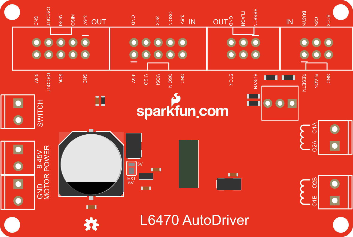
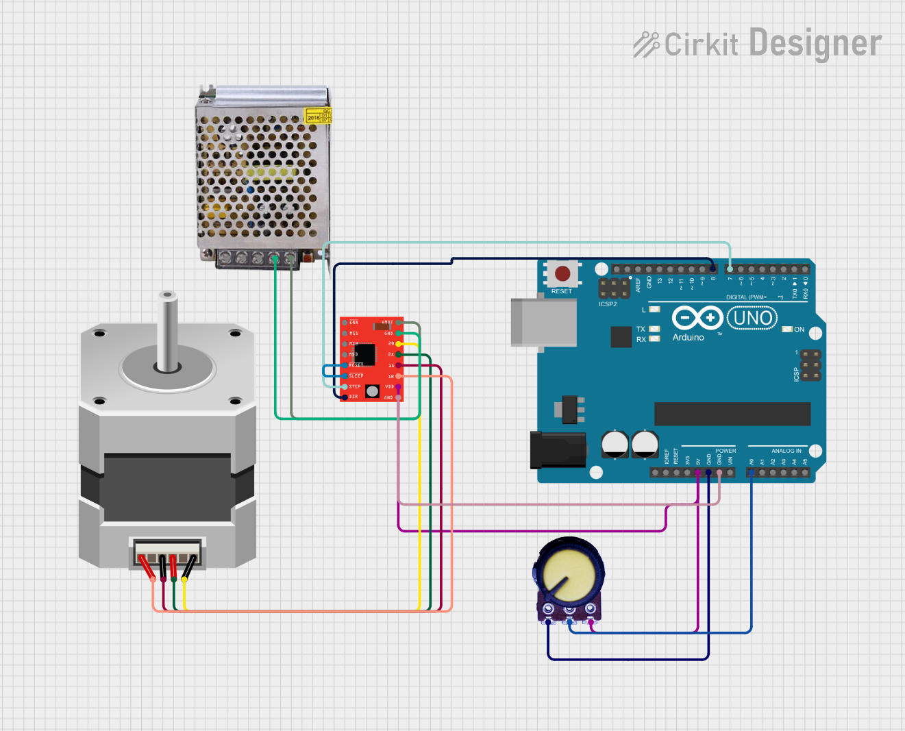
The SparkFun AutoDriver is a sophisticated stepper motor driver that offers a versatile solution for driving bipolar stepper motors in various applications. It is based on the STMicroelectronics L6470 chip, which provides advanced features such as adjustable current control, microstepping, and built-in overcurrent protection. This driver is suitable for projects requiring precise motor control, such as 3D printers, CNC machines, and robotics.

Explore Projects Built with SparkFun AutoDriver - Stepper Motor Driver (v10)

Use Cirkit Designer to design, explore, and prototype these projects online. Some projects support real-time simulation. Click "Open Project" to start designing instantly!
Teensy-Controlled Stepper Motor and Servo Actuation System
Image of Prototype Robotic Arm: A project utilizing SparkFun AutoDriver - Stepper Motor Driver (v10) in a practical application
This circuit controls a bipolar stepper motor using an A4988 Stepper Motor Driver, which is interfaced with a Teensy 4.1 microcontroller. The Teensy sends step and direction signals to the driver, while the driver's RESET and SLEEP pins are tied together, likely for simplified control. Additionally, the circuit includes an Adafruit PCA9685 PWM Servo Breakout board, which is connected to a servo motor and communicates with the Teensy via I2C, and both the driver and the breakout board are powered by separate power supplies with decoupling provided by an electrolytic capacitor.
Cirkit Designer LogoOpen Project in Cirkit Designer
Arduino UNO Controlled Stepper Motor with 12V Power Supply
Image of stepper motor: A project utilizing SparkFun AutoDriver - Stepper Motor Driver (v10) in a practical application
This circuit uses an Arduino UNO to control a bipolar stepper motor via a stepper driver. The Arduino sends direction and pulse signals to the stepper driver, which in turn drives the stepper motor using a 12V power supply. The motor runs for 10 seconds and then stops for 10 seconds in a continuous loop.
Cirkit Designer LogoOpen Project in Cirkit Designer
ESP32-Controlled Stepper and Servo Motor System with A4988 Driver and Micro Switch Feedback
Image of door_controller: A project utilizing SparkFun AutoDriver - Stepper Motor Driver (v10) in a practical application
This is a smart motor control circuit that uses an ESP32 microcontroller to drive a stepper motor via an A4988 driver and a servo motor for actuation tasks. It features WiFi connectivity for remote operation, position feedback via a micro switch, and is compatible with Home Assistant for smart home integration.
Cirkit Designer LogoOpen Project in Cirkit Designer
Arduino-Controlled Bipolar Stepper Motor with A4988 Driver
Image of steppermotor test: A project utilizing SparkFun AutoDriver - Stepper Motor Driver (v10) in a practical application
This circuit controls a bipolar stepper motor using an A4988 stepper motor driver, which is interfaced with an Arduino UNO microcontroller. The Arduino provides control signals for the direction (DIR) and stepping (STEP) of the motor, while a potentiometer connected to an analog input (A0) may be used for speed or position feedback. The motor driver is powered by a 12V power supply, and the RESET and SLEEP pins of the driver are connected together, likely to enable the motor driver to operate immediately upon power-up.
Cirkit Designer LogoOpen Project in Cirkit Designer

Explore Projects Built with SparkFun AutoDriver - Stepper Motor Driver (v10)

Use Cirkit Designer to design, explore, and prototype these projects online. Some projects support real-time simulation. Click "Open Project" to start designing instantly!
Image of Prototype Robotic Arm: A project utilizing SparkFun AutoDriver - Stepper Motor Driver (v10) in a practical application
Teensy-Controlled Stepper Motor and Servo Actuation System
This circuit controls a bipolar stepper motor using an A4988 Stepper Motor Driver, which is interfaced with a Teensy 4.1 microcontroller. The Teensy sends step and direction signals to the driver, while the driver's RESET and SLEEP pins are tied together, likely for simplified control. Additionally, the circuit includes an Adafruit PCA9685 PWM Servo Breakout board, which is connected to a servo motor and communicates with the Teensy via I2C, and both the driver and the breakout board are powered by separate power supplies with decoupling provided by an electrolytic capacitor.
Cirkit Designer LogoOpen Project in Cirkit Designer
Image of stepper motor: A project utilizing SparkFun AutoDriver - Stepper Motor Driver (v10) in a practical application
Arduino UNO Controlled Stepper Motor with 12V Power Supply
This circuit uses an Arduino UNO to control a bipolar stepper motor via a stepper driver. The Arduino sends direction and pulse signals to the stepper driver, which in turn drives the stepper motor using a 12V power supply. The motor runs for 10 seconds and then stops for 10 seconds in a continuous loop.
Cirkit Designer LogoOpen Project in Cirkit Designer
Image of door_controller: A project utilizing SparkFun AutoDriver - Stepper Motor Driver (v10) in a practical application
ESP32-Controlled Stepper and Servo Motor System with A4988 Driver and Micro Switch Feedback
This is a smart motor control circuit that uses an ESP32 microcontroller to drive a stepper motor via an A4988 driver and a servo motor for actuation tasks. It features WiFi connectivity for remote operation, position feedback via a micro switch, and is compatible with Home Assistant for smart home integration.
Cirkit Designer LogoOpen Project in Cirkit Designer
Image of steppermotor test: A project utilizing SparkFun AutoDriver - Stepper Motor Driver (v10) in a practical application
Arduino-Controlled Bipolar Stepper Motor with A4988 Driver
This circuit controls a bipolar stepper motor using an A4988 stepper motor driver, which is interfaced with an Arduino UNO microcontroller. The Arduino provides control signals for the direction (DIR) and stepping (STEP) of the motor, while a potentiometer connected to an analog input (A0) may be used for speed or position feedback. The motor driver is powered by a 12V power supply, and the RESET and SLEEP pins of the driver are connected together, likely to enable the motor driver to operate immediately upon power-up.
Cirkit Designer LogoOpen Project in Cirkit Designer

Common Applications and Use Cases

  • 3D Printing
  • CNC Machines
  • Robotics
  • Precision Positioning Systems
  • Automated Equipment

Technical Specifications

Key Technical Details

  • Motor Type: Bipolar Stepper
  • Maximum Current per Phase: 1.5A
  • Voltage Range: 8V to 45V
  • Microstepping: Up to 1/128
  • Communication: SPI for configuration and control, Step/Direction interface
  • Built-in Features: Overcurrent protection, thermal shutdown, under-voltage lockout

Pin Configuration and Descriptions

Pin Number Name Description
1 VMOT Motor power supply (8V to 45V)
2 GND Ground connection
3 B1 Motor coil B connection 1
4 B2 Motor coil B connection 2
5 A1 Motor coil A connection 1
6 A2 Motor coil A connection 2
7 VDD Logic power supply (3.3V or 5V)
8 STBY Standby pin (active low)
9 FLAG Fault flag output
10 BUSY Busy pin (active low)
11 SCK SPI clock input
12 SDI SPI data input
13 SDO SPI data output
14 CSN SPI chip select (active low)
15 STCK External clock input (optional)
16 STEP Step input
17 DIR Direction input
18 RESET Reset pin (active low)

Usage Instructions

How to Use the Component in a Circuit

  1. Power Connections:

    • Connect the motor power supply to the VMOT and GND pins.
    • Connect the logic power supply to the VDD and GND pins.
  2. Motor Connections:

    • Connect the bipolar stepper motor coils to the A1, A2, B1, and B2 pins.
  3. Control Connections:

    • For step/direction control, connect the STEP and DIR pins to the controlling microcontroller.
    • For SPI communication, connect the SCK, SDI, SDO, and CSN pins to the corresponding SPI pins on the microcontroller.
  4. Configuration:

    • Use the SPI interface to configure the AutoDriver settings such as current limit, step mode, and other parameters.
  5. Operation:

    • Send step pulses to the STEP pin to move the motor. Change the logic level of the DIR pin to control the direction.

Important Considerations and Best Practices

  • Ensure that the power supply voltage and current ratings are within the specifications of the AutoDriver.
  • Use a decoupling capacitor close to the VMOT and VDD pins to minimize voltage spikes.
  • Configure the current limit to match the stepper motor's specifications to prevent damage.
  • Avoid disconnecting the motor while the driver is powered to prevent damage to the driver.
  • Use proper heat sinking if operating the driver at high currents for extended periods.

Troubleshooting and FAQs

Common Issues

  • Motor not moving: Check power supply connections, motor connections, and SPI configuration.
  • Overheating: Ensure proper current settings and heat sinking.
  • Noise or erratic movement: Adjust the current limit and check for proper microstepping configuration.

Solutions and Tips for Troubleshooting

  • Verify all connections and solder joints.
  • Use the FLAG pin to diagnose fault conditions.
  • Ensure that the SPI communication is correctly established with the microcontroller.
  • Check the thermal and overcurrent protection settings.

FAQs

  • Q: Can I drive two motors simultaneously with one AutoDriver?

    • A: No, the AutoDriver is designed to control one bipolar stepper motor. You will need one driver per motor.
  • Q: What is the maximum step frequency?

    • A: The maximum step frequency depends on the motor and power supply characteristics. Refer to the L6470 datasheet for detailed timing information.
  • Q: How do I set the current limit?

    • A: The current limit is set via SPI commands. Refer to the L6470 datasheet and the SparkFun AutoDriver library for the correct commands.

Example Code for Arduino UNO

#include <SPI.h>
#include <SparkFunAutoDriver.h>

// Define the chip select pin for the AutoDriver
#define CSPin 10

// Create an instance of the AutoDriver
AutoDriver motor(CSPin);

void setup() {
  // Start the SPI bus
  SPI.begin();
  
  // Reset the AutoDriver
  motor.resetSettings();
  
  // Set the motor current limit (value depends on the motor)
  motor.setCurrent(100); // 1A current limit
  
  // Set the step mode (microstepping)
  motor.setStepMode(STEP_FS_128); // Full step with 1/128 microstepping
  
  // Enable the motor
  motor.enable();
}

void loop() {
  // Move the motor one step forward
  motor.move(FWD, 1);
  delay(100);
  
  // Move the motor one step backward
  motor.move(REV, 1);
  delay(100);
}

Note: The above code is a simple example to demonstrate basic motor movement. For more advanced features and configurations, refer to the SparkFun AutoDriver library documentation and the L6470 datasheet.