How to Use Modul Mikrokontroller: Examples, Pinouts, and Specs
Introduction
A microcontroller module is a compact integrated circuit designed to govern specific operations in embedded systems. It typically integrates a processor, memory, and input/output peripherals, enabling it to perform tasks such as controlling devices, processing data, and interfacing with other components. These modules are widely used in applications ranging from home automation and robotics to industrial control systems and IoT devices.
Explore Projects Built with Modul Mikrokontroller

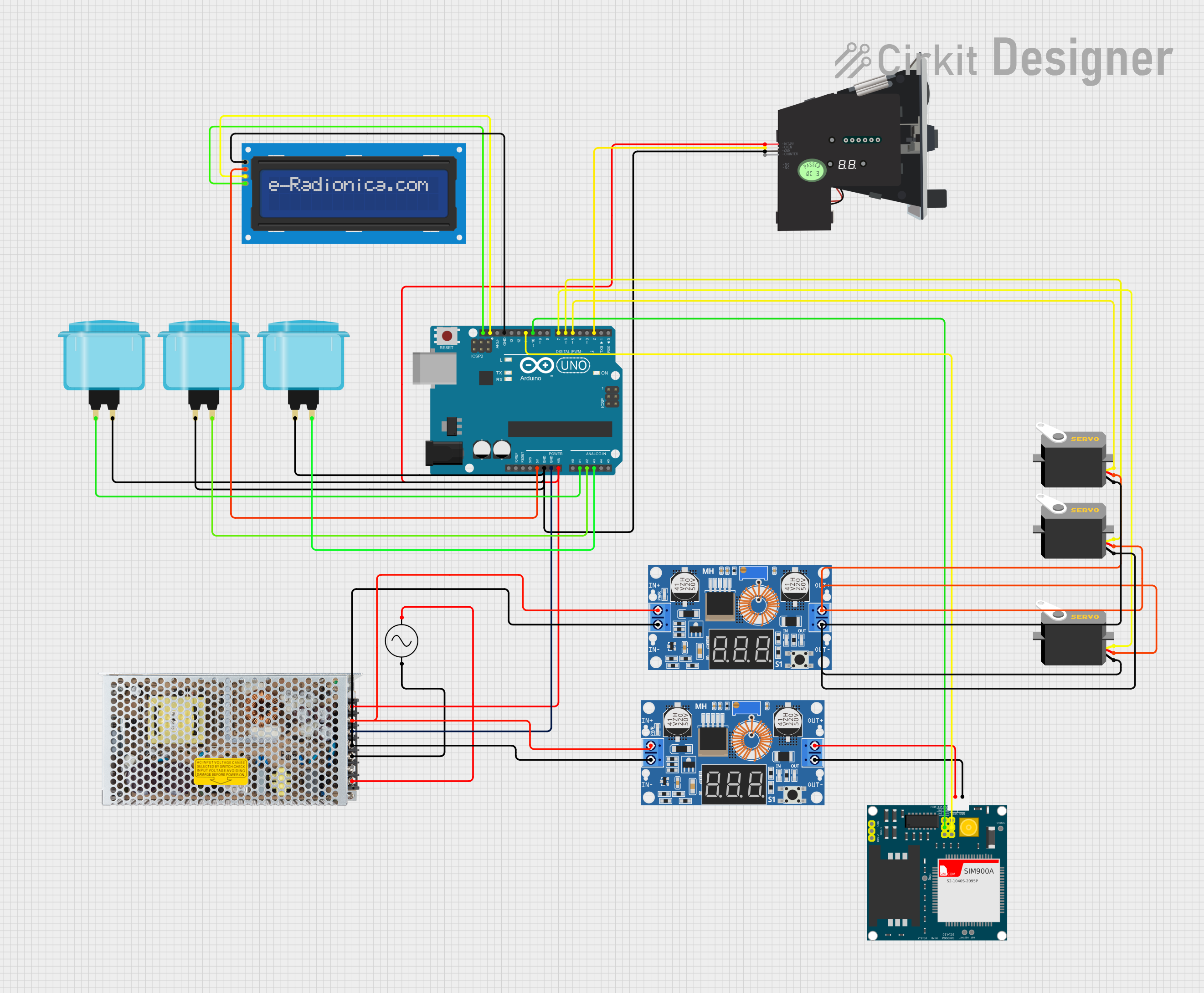
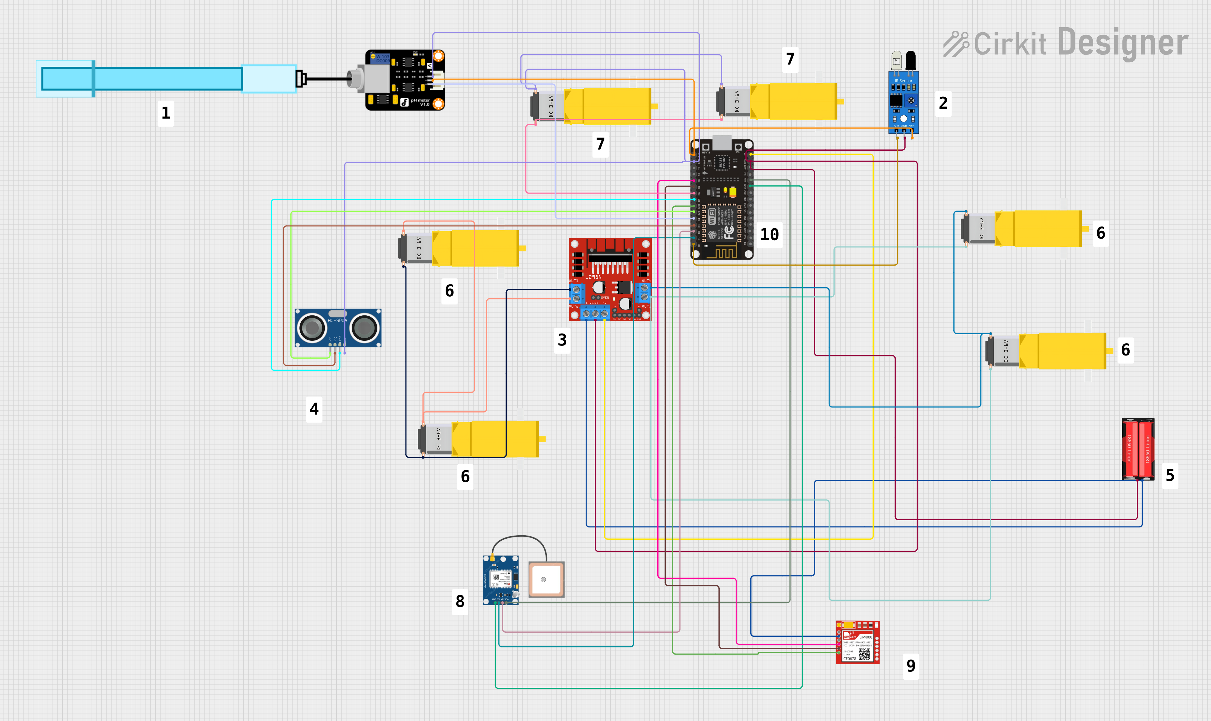

Explore Projects Built with Modul Mikrokontroller
Common Applications and Use Cases
- Home Automation: Controlling smart devices like lights, thermostats, and security systems.
- Robotics: Driving motors, reading sensors, and executing control algorithms.
- IoT Devices: Collecting and transmitting data to the cloud or other devices.
- Industrial Automation: Monitoring and controlling machinery and processes.
- Prototyping: Rapid development of embedded systems for testing and experimentation.
Technical Specifications
Below are the general technical specifications for a typical microcontroller module. Specific values may vary depending on the module model.
Key Technical Details
- Processor: 8-bit, 16-bit, or 32-bit CPU (e.g., ARM Cortex-M, AVR, or PIC).
- Operating Voltage: 3.3V or 5V (module-dependent).
- Clock Speed: Typically ranges from 8 MHz to 72 MHz or higher.
- Memory:
- Flash: 32 KB to 512 KB (for program storage).
- SRAM: 2 KB to 64 KB (for runtime data).
- I/O Pins: Digital and analog pins for interfacing with external components.
- Communication Protocols: UART, SPI, I2C, and sometimes USB.
- Power Consumption: Low-power modes available for energy-efficient applications.
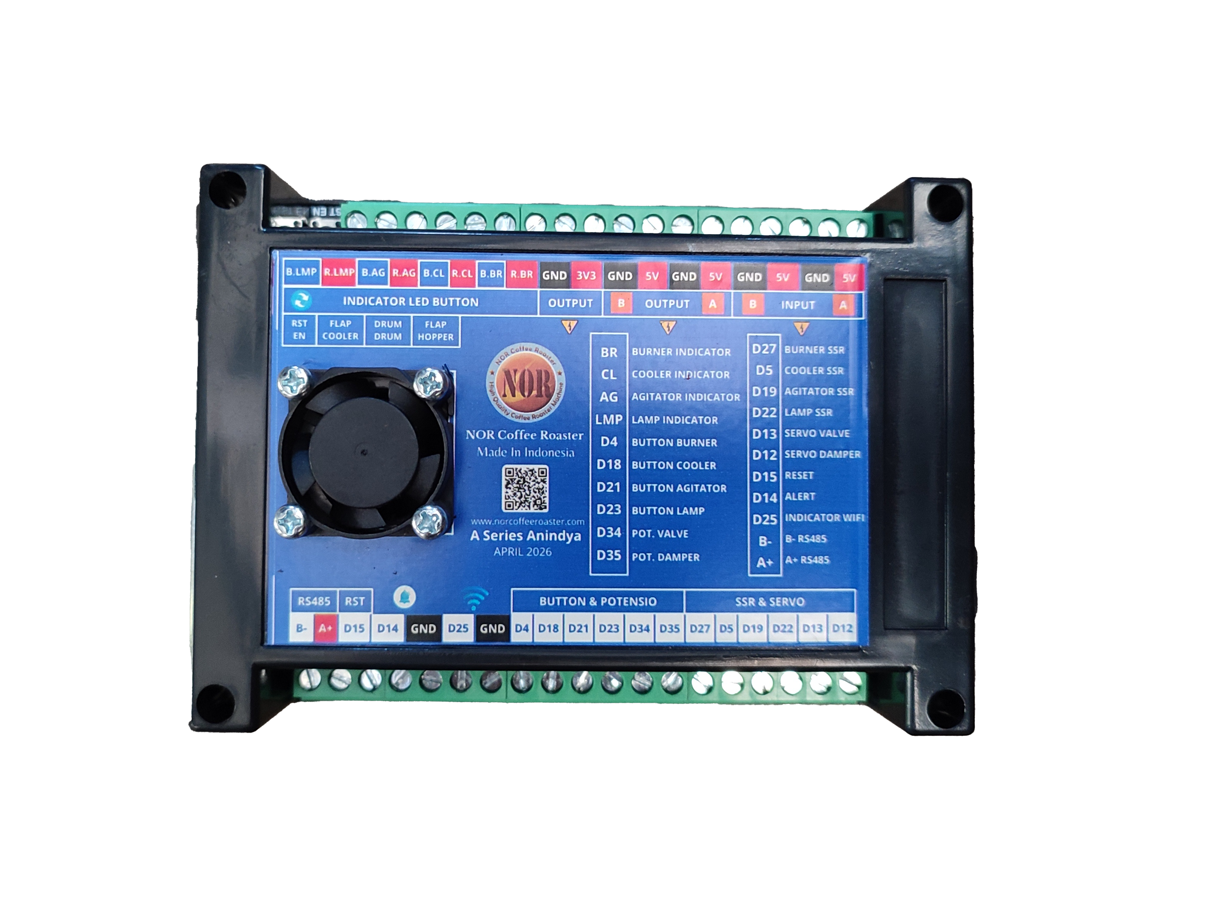
Pin Configuration and Descriptions
The pin configuration of a microcontroller module varies by model. Below is an example pinout for a generic microcontroller module:
| Pin | Name | Description |
|---|---|---|
| 1 | VCC | Power supply input (3.3V or 5V, depending on the module). |
| 2 | GND | Ground connection. |
| 3 | Digital I/O | General-purpose digital input/output pin. |
| 4 | Analog Input | Pin for reading analog signals (e.g., from sensors). |
| 5 | PWM Output | Pulse-width modulation output for controlling devices like motors or LEDs. |
| 6 | UART TX | Transmit pin for serial communication. |
| 7 | UART RX | Receive pin for serial communication. |
| 8 | I2C SDA | Data line for I2C communication. |
| 9 | I2C SCL | Clock line for I2C communication. |
| 10 | SPI MOSI | Master Out Slave In pin for SPI communication. |
| 11 | SPI MISO | Master In Slave Out pin for SPI communication. |
| 12 | SPI SCK | Clock pin for SPI communication. |
| 13 | Reset | Resets the microcontroller module. |
Usage Instructions
How to Use the Component in a Circuit
- Power the Module: Connect the VCC pin to a 3.3V or 5V power source (as specified for your module) and the GND pin to ground.
- Connect Peripherals: Use the digital and analog pins to interface with sensors, actuators, and other components.
- Program the Module: Write and upload code to the microcontroller using a compatible development environment (e.g., Arduino IDE).
- Establish Communication: Use UART, SPI, or I2C pins to communicate with other devices or modules.
Important Considerations and Best Practices
- Voltage Levels: Ensure that the input voltage matches the module's operating voltage to avoid damage.
- Pin Current Limits: Do not exceed the maximum current rating for I/O pins (typically 20-40 mA).
- Decoupling Capacitors: Place capacitors near the power pins to stabilize the power supply.
- Code Optimization: Optimize your code to minimize memory usage and improve performance.
- Static Protection: Handle the module carefully to avoid damage from electrostatic discharge (ESD).
Example Code for Arduino UNO
Below is an example of how to use a microcontroller module to blink an LED connected to a digital pin:
// Define the pin connected to the LED
const int ledPin = 13;

void setup() {
  // Set the LED pin as an output
  pinMode(ledPin, OUTPUT);
}

void loop() {
  // Turn the LED on
  digitalWrite(ledPin, HIGH);
  delay(1000); // Wait for 1 second

  // Turn the LED off
  digitalWrite(ledPin, LOW);
  delay(1000); // Wait for 1 second
}
Troubleshooting and FAQs
Common Issues Users Might Face
Module Not Powering On:
- Cause: Incorrect voltage or loose connections.
- Solution: Verify the power supply voltage and ensure all connections are secure.
Program Upload Fails:
- Cause: Incorrect COM port or missing drivers.
- Solution: Check the COM port in the development environment and install the required drivers.
Peripheral Not Responding:
- Cause: Incorrect pin connections or configuration.
- Solution: Double-check the wiring and ensure the pins are configured correctly in the code.
Overheating:
- Cause: Excessive current draw or short circuit.
- Solution: Reduce the load on the module and inspect for short circuits.
Solutions and Tips for Troubleshooting
- Debugging Tools: Use a multimeter or logic analyzer to diagnose electrical issues.
- Serial Monitor: Use the serial monitor in your development environment to debug code and monitor communication.
- Documentation: Refer to the module's datasheet for detailed specifications and guidelines.
- Community Support: Seek help from online forums and communities if you encounter persistent issues.