How to Use 0.96" OLED: Examples, Pinouts, and Specs
Introduction
The 0.96" OLED display module is a compact and versatile screen suitable for adding a visual interface to your electronics projects. With its Organic Light-Emitting Diode (OLED) technology, it provides high contrast, vibrant colors, and wide viewing angles. This display is commonly used in wearable devices, small instruments, and any application where a small yet clear display is required.
Explore Projects Built with 0.96" OLED


Explore Projects Built with 0.96" OLED
Common Applications and Use Cases
- Wearable devices
- Portable instruments
- User interfaces for small-scale projects
- Battery-powered applications due to low power consumption
Technical Specifications
Key Technical Details
- Display Type: OLED (Organic Light-Emitting Diode)
- Screen Size: 0.96 inches diagonally
- Resolution: 128x64 pixels
- Color Depth: Monochrome (typically blue or white)
- Interface: I2C or SPI (varies by model)
- Operating Voltage: 3.3V to 5V (check specific model)
- Current Consumption: 10-20mA (typical)
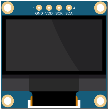
Pin Configuration and Descriptions
| Pin Number | Pin Name | Description |
|---|---|---|
| 1 | GND | Ground |
| 2 | VCC | Power supply (3.3V - 5V) |
| 3 | SCL | Serial Clock Line (I2C) or SPI Clock (SPI) |
| 4 | SDA | Serial Data Line (I2C) or SPI Data In (SPI) |
| 5 | RES | Reset (optional for some models) |
| 6 | DC | Data/Command (SPI only) |
| 7 | CS | Chip Select (SPI only) |
Usage Instructions
How to Use the Component in a Circuit
- Power Connections: Connect the VCC pin to a 3.3V or 5V power supply and the GND pin to the ground.
- Data Connections: For I2C, connect SCL to the I2C clock line and SDA to the I2C data line. For SPI, connect SCL, SDA, DC, and CS to the corresponding SPI pins on your microcontroller.
- Reset (Optional): The RES pin can be connected to a digital pin on your microcontroller to allow software reset of the display.
Important Considerations and Best Practices
- Ensure that the power supply voltage matches the requirements of your specific OLED module.
- Use pull-up resistors on the I2C lines if they are not included on the module.
- Avoid exposing the display to direct sunlight for extended periods to prevent damage.
- When using SPI, ensure that the correct data/command (DC) and chip select (CS) pins are used.
Example Code for Arduino UNO
#include <Wire.h>
#include <Adafruit_GFX.h>
#include <Adafruit_SSD1306.h>

// OLED display TWI address (usually 0x3C or 0x3D)
#define OLED_ADDR   0x3C
// Reset pin not used on 4-pin OLED module but required for library
#define OLED_RESET  -1
Adafruit_SSD1306 display(128, 64, &Wire, OLED_RESET);

void setup() {
  // Initialize with the I2C addr 0x3C (for the 128x64)
  if(!display.begin(SSD1306_SWITCHCAPVCC, OLED_ADDR)) {
    Serial.println(F("SSD1306 allocation failed"));
    for(;;); // Don't proceed, loop forever
  }
  display.display();
  delay(2000); // Pause for 2 seconds

  // Clear the buffer
  display.clearDisplay();

  // Draw a single pixel in white
  display.drawPixel(10, 10, WHITE);

  // Show the display buffer on the screen
  display.display();
}

void loop() {
  // Code to update the display continuously
}
Troubleshooting and FAQs
Common Issues Users Might Face
- Display not powering on: Check the power connections and ensure the voltage is within the specified range.
- No display or corrupted pixels: Verify the I2C/SPI connections and ensure that the correct communication protocol is selected.
- Dim display: Adjust the contrast or check if the power supply is able to deliver sufficient current.
Solutions and Tips for Troubleshooting
- Double-check wiring against the pin configuration table.
- Use example code to test the display before integrating it into your project.
- If using I2C, scan for the device address to ensure communication is established.
- For SPI, ensure that the correct pins are defined in your code for DC and CS.
FAQs
Q: Can I use this display with a 5V microcontroller? A: Yes, most 0.96" OLED displays are 5V tolerant, but always check the specifications of your particular module.
Q: How do I know if my OLED is using I2C or SPI? A: Check the pinout and the documentation provided by the manufacturer. I2C modules typically have fewer pins.
Q: Can I display images on the OLED? A: Yes, you can display bitmap images, but they need to be converted to a monochrome format suitable for the display's resolution.
Q: Is it possible to use multiple OLED displays with an Arduino? A: Yes, with I2C you can use multiple displays with different addresses. With SPI, you can use multiple displays by selecting different CS pins for each one.