Cirkit Designer Logo
Cirkit Designer
Your all-in-one circuit design IDE
Home / 
Component Documentation

How to Use RTC-DS1302: Examples, Pinouts, and Specs

Image of RTC-DS1302
Cirkit Designer LogoDesign with RTC-DS1302 in Cirkit Designer

Introduction

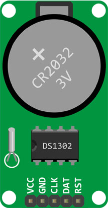
The RTC-DS1302 is a real-time clock (RTC) module that provides accurate timekeeping capabilities. It is equipped with an integrated circuit (IC) DS1302 which communicates via a simple serial interface. The module includes a small coin cell battery that maintains the time when the main power is off. Common applications include clocks, data loggers, timers, and other devices that require an accurate time reference.

Explore Projects Built with RTC-DS1302

Use Cirkit Designer to design, explore, and prototype these projects online. Some projects support real-time simulation. Click "Open Project" to start designing instantly!
Arduino UNO with DS1307 RTC Controlled LED Lighting System
Image of li8: A project utilizing RTC-DS1302 in a practical application
This circuit features an Arduino UNO connected to a DS1307 Real Time Clock (RTC) module for timekeeping and a red LED with a series resistor for indication purposes. The Arduino communicates with the RTC via I2C (using A4 and A5 pins for SDA and SCL, respectively), and controls the LED connected to digital pin D8 through a 330-ohm resistor. The embedded code sets the RTC time, checks the current time, and turns the LED on or off based on the specified time condition (between 11:00 AM and 11:43 AM).
Cirkit Designer LogoOpen Project in Cirkit Designer
Arduino UNO Real-Time Clock with DS1307 RTC Module
Image of rrtc: A project utilizing RTC-DS1302 in a practical application
This circuit interfaces an Arduino UNO with a DS1307 Real-Time Clock (RTC) module. The Arduino communicates with the RTC module using the I2C protocol, with connections from A4 to SDA and A5 to SCL.
Cirkit Designer LogoOpen Project in Cirkit Designer
Arduino Nano Based Real-Time Clock Display with TM1637
Image of 7segmant: A project utilizing RTC-DS1302 in a practical application
This circuit features an Arduino Nano interfacing with a DS3231 Real-Time Clock for timekeeping and a TM1637 display module for visual output. The Arduino facilitates I2C communication with the RTC and controls the display using digital IO, serving as the central processing unit for a digital clock or timer application.
Cirkit Designer LogoOpen Project in Cirkit Designer
Arduino UNO Controlled Relay with DS3231 RTC
Image of Hooter connections: A project utilizing RTC-DS1302 in a practical application
This circuit features an Arduino UNO microcontroller connected to a DS3231 Real Time Clock (RTC) module and a 12V single-channel relay. The Arduino provides power to both the RTC and the relay, and it communicates with the RTC via I2C using the SDA and SCL lines connected to A4 and A5 respectively. The relay is controlled by the Arduino through a digital output on pin D13, allowing the Arduino to switch external loads on and off based on time events managed by the RTC.
Cirkit Designer LogoOpen Project in Cirkit Designer

Explore Projects Built with RTC-DS1302

Use Cirkit Designer to design, explore, and prototype these projects online. Some projects support real-time simulation. Click "Open Project" to start designing instantly!
Image of li8: A project utilizing RTC-DS1302 in a practical application
Arduino UNO with DS1307 RTC Controlled LED Lighting System
This circuit features an Arduino UNO connected to a DS1307 Real Time Clock (RTC) module for timekeeping and a red LED with a series resistor for indication purposes. The Arduino communicates with the RTC via I2C (using A4 and A5 pins for SDA and SCL, respectively), and controls the LED connected to digital pin D8 through a 330-ohm resistor. The embedded code sets the RTC time, checks the current time, and turns the LED on or off based on the specified time condition (between 11:00 AM and 11:43 AM).
Cirkit Designer LogoOpen Project in Cirkit Designer
Image of rrtc: A project utilizing RTC-DS1302 in a practical application
Arduino UNO Real-Time Clock with DS1307 RTC Module
This circuit interfaces an Arduino UNO with a DS1307 Real-Time Clock (RTC) module. The Arduino communicates with the RTC module using the I2C protocol, with connections from A4 to SDA and A5 to SCL.
Cirkit Designer LogoOpen Project in Cirkit Designer
Image of 7segmant: A project utilizing RTC-DS1302 in a practical application
Arduino Nano Based Real-Time Clock Display with TM1637
This circuit features an Arduino Nano interfacing with a DS3231 Real-Time Clock for timekeeping and a TM1637 display module for visual output. The Arduino facilitates I2C communication with the RTC and controls the display using digital IO, serving as the central processing unit for a digital clock or timer application.
Cirkit Designer LogoOpen Project in Cirkit Designer
Image of Hooter connections: A project utilizing RTC-DS1302 in a practical application
Arduino UNO Controlled Relay with DS3231 RTC
This circuit features an Arduino UNO microcontroller connected to a DS3231 Real Time Clock (RTC) module and a 12V single-channel relay. The Arduino provides power to both the RTC and the relay, and it communicates with the RTC via I2C using the SDA and SCL lines connected to A4 and A5 respectively. The relay is controlled by the Arduino through a digital output on pin D13, allowing the Arduino to switch external loads on and off based on time events managed by the RTC.
Cirkit Designer LogoOpen Project in Cirkit Designer

Technical Specifications

Key Technical Details

  • Timekeeping Accuracy: ±2 minutes/month at 25°C
  • Operating Voltage: 2.0V to 5.5V
  • Battery Backup Voltage: 1.3V to 5.5V
  • Operating Current: 2mA (max)
  • Battery Current: 300nA (typical)
  • Operating Temperature: 0°C to +70°C
  • Interface: Serial (Simple 3-wire interface)

Pin Configuration and Descriptions

Pin Number Name Description
1 VCC Power supply (2.0V to 5.5V)
2 GND Ground
3 CLK Clock input for serial interface
4 DAT Data input/output for serial interface
5 RST Reset input for serial interface
6 NC Not connected
7 NC Not connected
8 BAT Battery input for backup

Usage Instructions

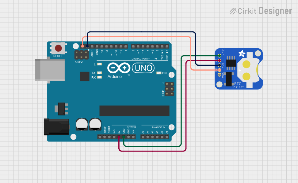
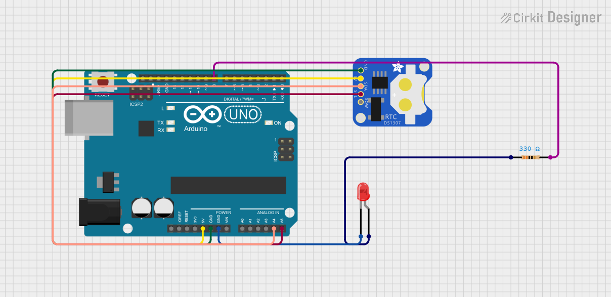
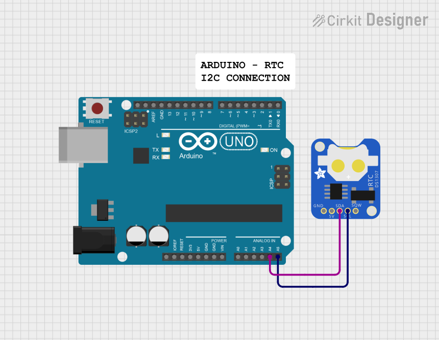
Interfacing with a Circuit

  1. Power Connections: Connect VCC to a 2.0V to 5.5V power supply and GND to the ground.
  2. Serial Interface: Connect CLK, DAT, and RST to the microcontroller's digital pins.
  3. Battery Backup: Install a coin cell battery to the BAT pin to maintain timekeeping during power loss.

Important Considerations and Best Practices

  • Ensure that the power supply voltage does not exceed 5.5V to prevent damage.
  • The battery should be installed correctly with the positive side facing up.
  • Use pull-up resistors on the data line if required by the microcontroller.
  • Avoid placing the module near heat sources or in environments with high humidity.

Example Code for Arduino UNO

#include <DS1302.h>

// Initialize the DS1302
// RST pin, DAT pin, CLK pin
DS1302 rtc(7, 6, 5);

void setup() {
  // Set the clock to run-mode, and disable the write protection
  rtc.halt(false);
  rtc.writeProtect(false);

  // Setup Serial connection
  Serial.begin(9600);

  // The following lines can be uncommented to set the date and time
  // rtc.setDOW(FRIDAY);        // Set Day-of-Week to FRIDAY
  // rtc.setTime(12, 0, 0);     // Set the time to 12:00:00 (24hr format)
  // rtc.setDate(6, 8, 2010);   // Set the date to August 6th, 2010
}

void loop() {
  // Get the current time and date from the RTC
  Serial.print(rtc.getDOWStr());
  Serial.print(" ");
  
  // Print the time
  Serial.print(rtc.getTimeStr());
  Serial.print(" -- ");

  // Print the date
  Serial.println(rtc.getDateStr());

  // Wait one second before repeating :)
  delay (1000);
}

Troubleshooting and FAQs

Common Issues

  • Time not accurate: Ensure the battery is installed correctly and has charge.
  • Module not responding: Check the wiring, especially the serial interface connections.
  • Time resets on power cycle: Verify that the battery is present and functioning.

Solutions and Tips for Troubleshooting

  • Double-check the connections and ensure that the correct pins are used.
  • Replace the battery if the module fails to keep time after power is removed.
  • If using long wires, ensure they are securely connected and consider using shielded cables to reduce noise.

FAQs

Q: Can the RTC-DS1302 be used in low-power applications? A: Yes, the RTC-DS1302 has a low-power consumption mode and can be used in battery-powered applications.

Q: How do I set the time on the RTC-DS1302? A: You can set the time by using the rtc.setTime() function in your code, as shown in the example above.

Q: What is the lifespan of the battery? A: The lifespan of the battery depends on the quality and type of battery used, but typically it can last for several years.

Q: Does the RTC-DS1302 account for leap years? A: Yes, the DS1302 chip has an automatic leap year compensation valid up to the year 2100.

Q: Can I use the RTC-DS1302 with other microcontrollers besides Arduino? A: Yes, the RTC-DS1302 can be interfaced with any microcontroller that supports a serial interface. Adjustments to the code may be necessary for different platforms.