How to Use ky-027.1: Examples, Pinouts, and Specs

Introduction
The KY-027.1 is a digital infrared obstacle avoidance sensor module designed for detecting objects in its proximity. It operates by emitting infrared light through an infrared LED and detecting the reflected light using a phototransistor. When an object is detected, the module outputs a digital signal, making it easy to interface with microcontrollers and other digital systems.
Explore Projects Built with ky-027.1
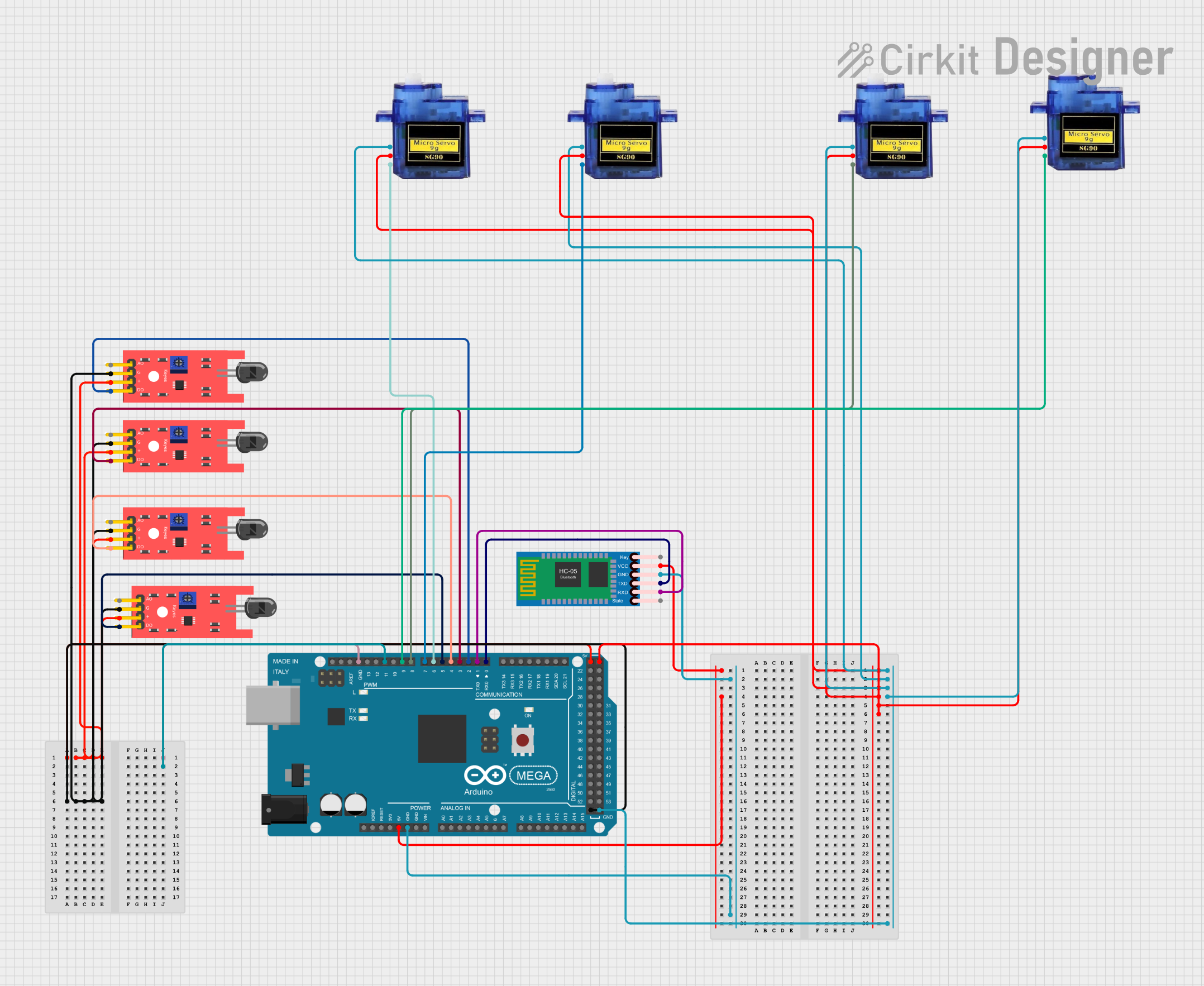
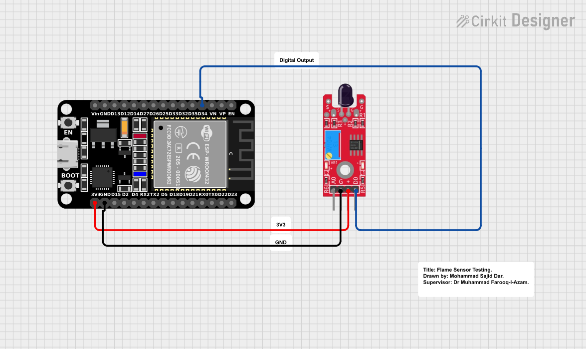


Explore Projects Built with ky-027.1
Common Applications and Use Cases
- Obstacle detection in robotics
- Line-following robots
- Proximity sensing in automation systems
- Object detection in conveyor belts
- Smart home applications, such as automatic doors or lighting systems
Technical Specifications
The KY-027.1 module is compact and easy to use, with the following key specifications:
| Parameter | Value |
|---|---|
| Operating Voltage | 3.3V to 5V |
| Output Type | Digital (High/Low) |
| Detection Range | 2 cm to 30 cm (adjustable) |
| Detection Angle | ~35° |
| Current Consumption | ~20 mA |
| Dimensions | 32mm x 14mm x 8mm |
Pin Configuration and Descriptions
The KY-027.1 module has three pins for easy interfacing:
| Pin | Name | Description |
|---|---|---|
| 1 | VCC | Connect to the positive supply voltage (3.3V to 5V). |
| 2 | GND | Connect to the ground of the power supply. |
| 3 | OUT | Digital output pin. Outputs HIGH (1) when no obstacle is detected, and LOW (0) when an obstacle is detected. |
Usage Instructions
How to Use the KY-027.1 in a Circuit
- Power the Module: Connect the
VCCpin to a 3.3V or 5V power source and theGNDpin to the ground. - Connect the Output: Connect the
OUTpin to a digital input pin of a microcontroller (e.g., Arduino UNO) or a digital logic circuit. - Adjust the Sensitivity: Use the onboard potentiometer to adjust the detection range and sensitivity of the sensor. Turn the potentiometer clockwise to increase sensitivity and counterclockwise to decrease it.
- Read the Output: Monitor the
OUTpin. It will output:- HIGH (1) when no obstacle is detected.
- LOW (0) when an obstacle is detected within the sensor's range.
Important Considerations and Best Practices
- Ambient Light Interference: The sensor may be affected by strong ambient light. Use it in controlled lighting conditions for optimal performance.
- Mounting Position: Ensure the sensor is mounted at an appropriate angle and height for the intended application.
- Power Supply: Use a stable power supply to avoid erratic behavior.
- Avoid Overexposure: Prolonged exposure to direct sunlight or strong infrared sources may degrade the sensor's performance.
Example: Connecting KY-027.1 to an Arduino UNO
Below is an example of how to connect and use the KY-027.1 with an Arduino UNO:
Circuit Diagram
- Connect the
VCCpin of the KY-027.1 to the 5V pin of the Arduino. - Connect the
GNDpin of the KY-027.1 to the GND pin of the Arduino. - Connect the
OUTpin of the KY-027.1 to digital pin 2 of the Arduino.
Arduino Code
// KY-027.1 Obstacle Avoidance Sensor Example
// Connect the OUT pin of the KY-027.1 to Arduino digital pin 2

const int sensorPin = 2;  // KY-027.1 OUT pin connected to digital pin 2
const int ledPin = 13;    // Onboard LED pin for visual feedback

void setup() {
  pinMode(sensorPin, INPUT);  // Set sensor pin as input
  pinMode(ledPin, OUTPUT);    // Set LED pin as output
  Serial.begin(9600);         // Initialize serial communication
}

void loop() {
  int sensorValue = digitalRead(sensorPin);  // Read the sensor output

  if (sensorValue == LOW) {
    // Obstacle detected
    digitalWrite(ledPin, HIGH);  // Turn on the LED
    Serial.println("Obstacle detected!");
  } else {
    // No obstacle
    digitalWrite(ledPin, LOW);   // Turn off the LED
    Serial.println("No obstacle.");
  }

  delay(100);  // Small delay for stability
}
Troubleshooting and FAQs
Common Issues and Solutions
The sensor is not detecting obstacles:
- Ensure the module is powered correctly (check VCC and GND connections).
- Adjust the sensitivity using the onboard potentiometer.
- Verify that the obstacle is within the detection range (2 cm to 30 cm).
False detections or erratic behavior:
- Check for strong ambient light or infrared interference.
- Use a stable power supply to avoid noise in the output signal.
Output pin always HIGH or LOW:
- Inspect the wiring and ensure the
OUTpin is connected to the correct microcontroller pin. - Verify that the phototransistor and infrared LED are functioning properly.
- Inspect the wiring and ensure the
FAQs
Q: Can the KY-027.1 detect transparent objects?
A: The sensor may struggle to detect transparent or highly reflective objects due to insufficient reflected infrared light.
Q: How do I increase the detection range?
A: Adjust the onboard potentiometer clockwise to increase the sensitivity and detection range.
Q: Can I use the KY-027.1 with a 3.3V microcontroller?
A: Yes, the KY-027.1 operates within a voltage range of 3.3V to 5V, making it compatible with 3.3V systems.
Q: What is the maximum detection angle of the sensor?
A: The KY-027.1 has a detection angle of approximately 35°, which is suitable for most obstacle detection applications.