
How to Use Hirose DF13A 7-Pin Header (Diagram Adapter): Examples, Pinouts, and Specs
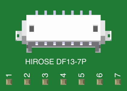
 Design with Hirose DF13A 7-Pin Header (Diagram Adapter) in Cirkit Designer
Introduction
The Hirose DF13A 7-Pin Header is a compact and reliable connector designed for secure and efficient connections in electronic circuits. Manufactured by Hirose Electric, this 7-pin header is widely used in applications requiring robust and space-saving interconnections. Its design ensures durability and consistent performance, making it a popular choice for interfacing with sensors, microcontrollers, and other electronic components.
Explore Projects Built with Hirose DF13A 7-Pin Header (Diagram Adapter)
 Open Project in Cirkit Designer
 Open Project in Cirkit Designer
 Open Project in Cirkit Designer
 Open Project in Cirkit Designer
Explore Projects Built with Hirose DF13A 7-Pin Header (Diagram Adapter)
Open Project in Cirkit DesignerOpen Project in Cirkit DesignerOpen Project in Cirkit DesignerOpen Project in Cirkit DesignerCommon Applications and Use Cases
- Interfacing sensors and modules with microcontrollers
- Providing secure connections in compact electronic devices
- Used in robotics, IoT devices, and embedded systems
- Ideal for prototyping and production-grade circuit designs
Technical Specifications
The Hirose DF13A 7-Pin Header is designed to meet the needs of modern electronic systems. Below are its key technical details:
Key Specifications
| Parameter | Value |
|---|---|
| Manufacturer | Hirose Electric |
| Number of Pins | 7 |
| Pitch (Pin Spacing) | 1.25 mm |
| Rated Current | 1 A per pin |
| Rated Voltage | 100 V AC/DC |
| Operating Temperature | -35°C to +85°C |
| Contact Resistance | 30 mΩ max |
| Insulation Resistance | 1000 MΩ min |
| Mounting Type | Through-hole or SMT |
| Material (Housing) | Polyamide (UL94V-0 rated) |
| Contact Material | Phosphor Bronze with Tin Plating |
Pin Configuration and Descriptions
The DF13A 7-Pin Header features a straightforward pin layout. Below is the pin configuration:
| Pin Number | Description | Notes |
|---|---|---|
| 1 | Signal/Power Line 1 | General-purpose connection |
| 2 | Signal/Power Line 2 | General-purpose connection |
| 3 | Signal/Power Line 3 | General-purpose connection |
| 4 | Signal/Power Line 4 | General-purpose connection |
| 5 | Signal/Power Line 5 | General-purpose connection |
| 6 | Signal/Power Line 6 | General-purpose connection |
| 7 | Signal/Power Line 7 | General-purpose connection |
Note: Pin assignments may vary depending on the specific application. Always refer to your circuit design or datasheet for proper pin usage.
Usage Instructions
The Hirose DF13A 7-Pin Header is easy to integrate into electronic circuits. Follow the steps below for proper usage:
How to Use the Component in a Circuit
Soldering the Header:
- Align the header pins with the corresponding holes on the PCB.
- Use a soldering iron and solder to securely attach each pin to the PCB pads.
- Ensure no solder bridges form between adjacent pins.
Connecting to a Mating Connector:
- Use a compatible Hirose DF13 series connector for the mating side.
- Insert the mating connector into the header until it clicks into place, ensuring a secure connection.
Wiring:
- Connect wires to the mating connector as per your circuit design.
- Double-check the pin assignments to avoid incorrect connections.
Important Considerations and Best Practices
- Avoid Overcurrent: Do not exceed the rated current of 1 A per pin to prevent overheating or damage.
- Secure Mounting: Ensure the header is firmly soldered to the PCB to avoid loose connections.
- Proper Alignment: When connecting the mating connector, align it carefully to avoid bending or damaging the pins.
- Environmental Conditions: Use the header within the specified operating temperature range (-35°C to +85°C).
Example: Using with an Arduino UNO
The DF13A 7-Pin Header can be used to interface sensors or modules with an Arduino UNO. Below is an example of connecting a sensor via the header:
Circuit Setup
- Solder the DF13A 7-Pin Header to the PCB.
- Connect the sensor's output pins to the header's pins.
- Use jumper wires to connect the header pins to the Arduino UNO's GPIO pins.
Sample Arduino Code
// Example: Reading data from a sensor connected via DF13A 7-Pin Header
const int sensorPin = A0; // Pin connected to the sensor's output

void setup() {
  Serial.begin(9600); // Initialize serial communication
  pinMode(sensorPin, INPUT); // Set the sensor pin as input
}

void loop() {
  int sensorValue = analogRead(sensorPin); // Read sensor value
  Serial.print("Sensor Value: ");
  Serial.println(sensorValue); // Print the sensor value to the Serial Monitor
  delay(500); // Wait for 500 ms before the next reading
}
Note: Adjust the pin assignments and code logic based on your specific sensor and application.
Troubleshooting and FAQs
Common Issues and Solutions
| Issue | Possible Cause | Solution |
|---|---|---|
| Loose connection | Improper soldering or alignment | Re-solder the header securely. |
| Signal interference or noise | Poor grounding or shielding | Ensure proper grounding and use shielded cables if necessary. |
| Overheating of pins | Exceeding current rating | Reduce the current load or distribute it across multiple pins. |
| Connector not fitting properly | Misalignment or incompatible part | Verify compatibility and align carefully before connecting. |
FAQs
Can I use the DF13A 7-Pin Header for high-frequency signals?
- Yes, but ensure proper grounding and shielding to minimize signal interference.
What tools are recommended for soldering this header?
- Use a fine-tip soldering iron and high-quality solder for precise and reliable connections.
Is the DF13A 7-Pin Header compatible with other Hirose DF13 series connectors?
- Yes, it is designed to mate with other connectors in the DF13 series.
Can I use this header in outdoor applications?
- The header is not weatherproof. For outdoor use, ensure it is enclosed in a protective housing.
By following this documentation, you can effectively integrate the Hirose DF13A 7-Pin Header into your electronic projects and ensure reliable performance.