
Cirkit Designer
Your all-in-one circuit design IDE
Home /
Component Documentation
How to Use 10-DOF IMU L3GD20H + LSM303 + BMP180: Examples, Pinouts, and Specs
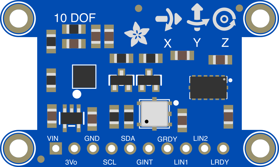
 Design with 10-DOF IMU L3GD20H + LSM303 + BMP180 in Cirkit Designer
Introduction
The 10-DOF IMU L3GD20H + LSM303 + BMP180 (Adafruit Part ID: 1604) is a compact and versatile sensor module that integrates multiple sensing capabilities into a single board. It combines a 3-axis gyroscope (L3GD20H), a 3-axis accelerometer, a 3-axis magnetometer (LSM303), and a barometric pressure sensor (BMP180). This makes it ideal for applications requiring motion tracking, orientation sensing, and environmental monitoring.
Explore Projects Built with 10-DOF IMU L3GD20H + LSM303 + BMP180
Raspberry Pi 5-Based Multi-Sensor IMU System with MPU-6050 and LSM303c
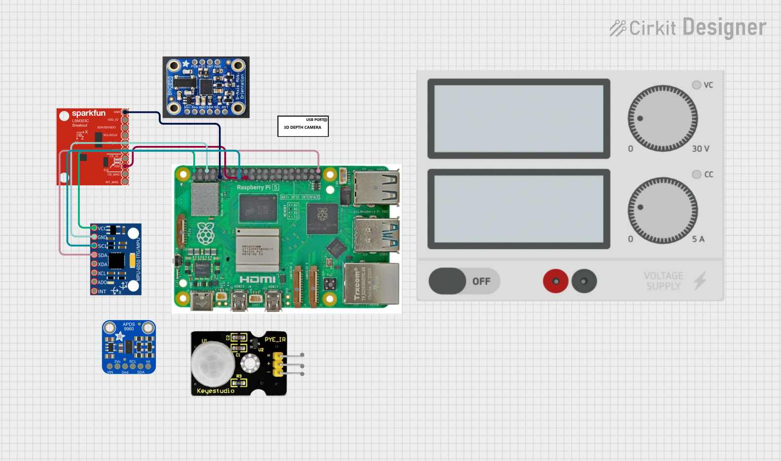
This circuit integrates a Raspberry Pi 5 with multiple sensors, including an MPU-6050 accelerometer and gyroscope, and an LSM303c 6DOF IMU, to collect and process motion and orientation data. The Raspberry Pi serves as the central processing unit, interfacing with the sensors via GPIO pins and providing power to them.
Open Project in Cirkit DesignerESP32-Based Weather Station with MPU-6050 and BMP280 Sensors
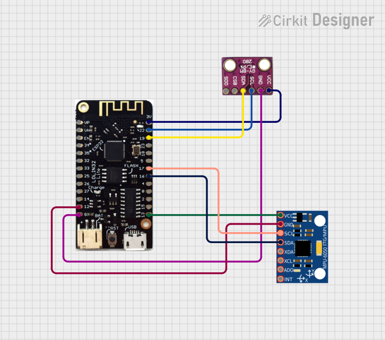
This circuit integrates an MPU-6050 accelerometer and gyroscope sensor and a BMP280 barometric pressure sensor with an ESP32 microcontroller. The ESP32 reads data from both sensors via I2C communication to potentially monitor environmental conditions and motion.
Open Project in Cirkit DesignerESP32-Controlled Multi-MPU6050 and MPU9250 IMU Data Aggregator
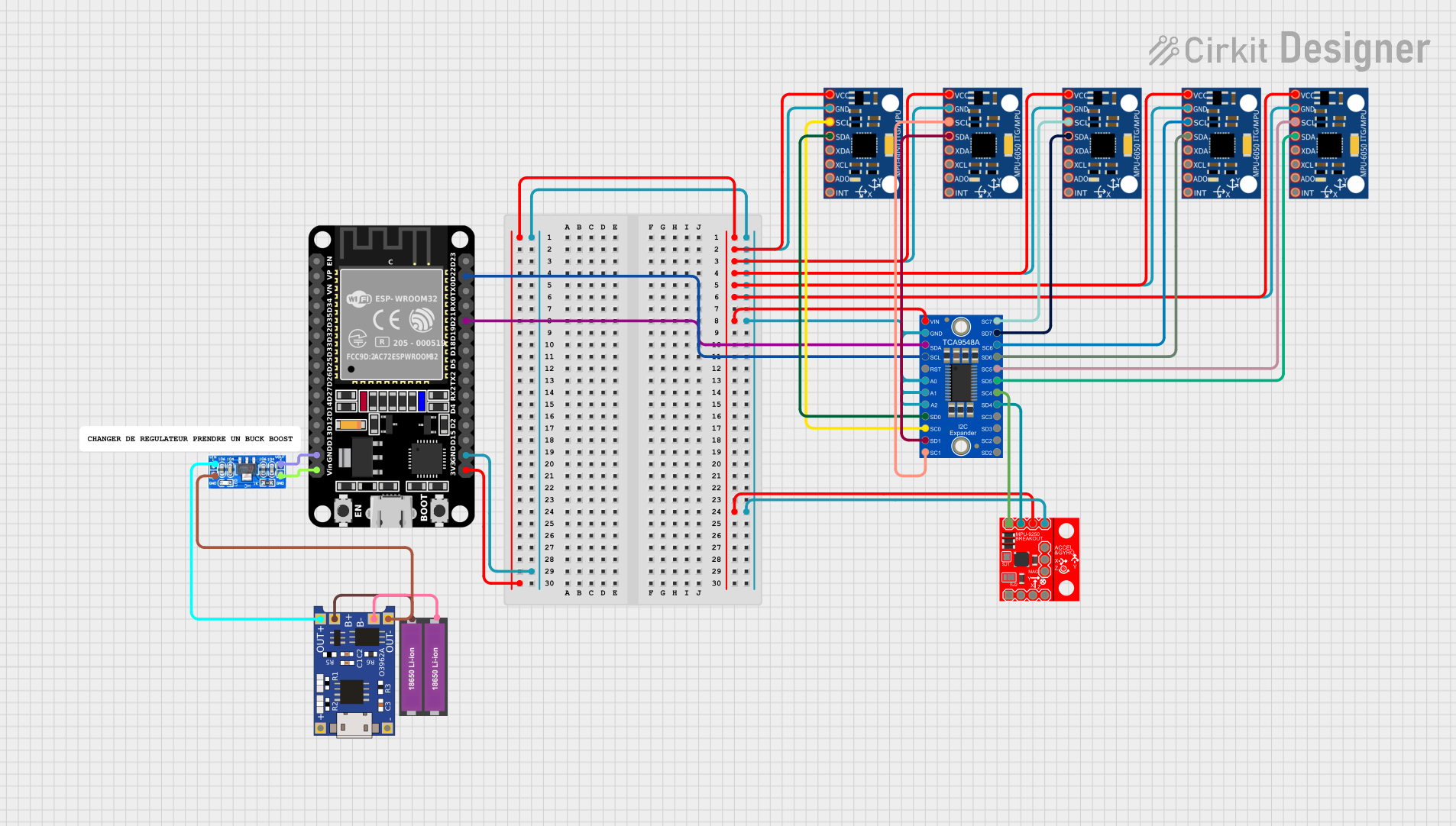
This circuit features an ESP32 microcontroller interfaced with multiple MPU-6050 sensors and a single MPU-9250 sensor through an Adafruit TCA9548A I2C multiplexer, allowing for the reading of multiple inertial measurement units (IMUs) over the same I2C bus. The ESP32 collects and processes acceleration and gyroscopic data from the sensors to calculate angles in the X and Y axes. Power management is handled by a TP4056 charging module and an AMS1117 voltage regulator, which together with two 18650 Li-ion batteries, provide a stable power supply for the microcontroller and sensors.
Open Project in Cirkit DesignerBattery-Powered Arduino UNO with BNO085 IMU and Bluetooth HC-06 for Orientation Tracking
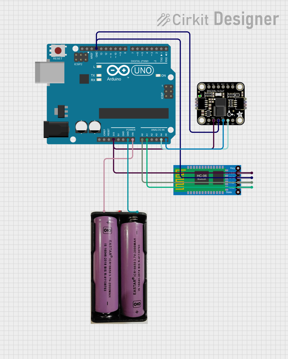
This circuit integrates an Arduino UNO with an Adafruit BNO085 9-DOF Orientation IMU and a Bluetooth HC-06 module. The Arduino reads orientation data from the IMU via I2C and transmits it over Bluetooth, powered by a 7.4V battery.
Open Project in Cirkit DesignerExplore Projects Built with 10-DOF IMU L3GD20H + LSM303 + BMP180
Raspberry Pi 5-Based Multi-Sensor IMU System with MPU-6050 and LSM303c
This circuit integrates a Raspberry Pi 5 with multiple sensors, including an MPU-6050 accelerometer and gyroscope, and an LSM303c 6DOF IMU, to collect and process motion and orientation data. The Raspberry Pi serves as the central processing unit, interfacing with the sensors via GPIO pins and providing power to them.
Open Project in Cirkit DesignerESP32-Based Weather Station with MPU-6050 and BMP280 Sensors
This circuit integrates an MPU-6050 accelerometer and gyroscope sensor and a BMP280 barometric pressure sensor with an ESP32 microcontroller. The ESP32 reads data from both sensors via I2C communication to potentially monitor environmental conditions and motion.
Open Project in Cirkit DesignerESP32-Controlled Multi-MPU6050 and MPU9250 IMU Data Aggregator
This circuit features an ESP32 microcontroller interfaced with multiple MPU-6050 sensors and a single MPU-9250 sensor through an Adafruit TCA9548A I2C multiplexer, allowing for the reading of multiple inertial measurement units (IMUs) over the same I2C bus. The ESP32 collects and processes acceleration and gyroscopic data from the sensors to calculate angles in the X and Y axes. Power management is handled by a TP4056 charging module and an AMS1117 voltage regulator, which together with two 18650 Li-ion batteries, provide a stable power supply for the microcontroller and sensors.
Open Project in Cirkit DesignerBattery-Powered Arduino UNO with BNO085 IMU and Bluetooth HC-06 for Orientation Tracking
This circuit integrates an Arduino UNO with an Adafruit BNO085 9-DOF Orientation IMU and a Bluetooth HC-06 module. The Arduino reads orientation data from the IMU via I2C and transmits it over Bluetooth, powered by a 7.4V battery.
Open Project in Cirkit DesignerCommon Applications
- Robotics and drone navigation
- Wearable devices for motion tracking
- Environmental monitoring systems
- Virtual reality (VR) and augmented reality (AR) systems
- Scientific experiments and data logging
Technical Specifications
Key Technical Details
| Parameter | Specification |
|---|---|
| Operating Voltage | 3.3V to 5V |
| Communication Interface | I2C (default), SPI (optional for L3GD20H only) |
| Gyroscope (L3GD20H) Range | ±250, ±500, ±2000 degrees/second |
| Accelerometer (LSM303) Range | ±2g, ±4g, ±8g, ±16g |
| Magnetometer (LSM303) Range | ±1.3 to ±8.1 gauss |
| Barometric Pressure (BMP180) | 300 to 1100 hPa (hectopascals) |
| Temperature Sensor Range | -40°C to +85°C |
| Dimensions | 20mm x 20mm x 3mm |
Pin Configuration and Descriptions
| Pin Name | Description |
|---|---|
| VIN | Power input (3.3V to 5V) |
| GND | Ground |
| SDA | I2C data line |
| SCL | I2C clock line |
| CS | Chip select for SPI communication (optional, used with L3GD20H) |
| SDO | SPI data output (optional, used with L3GD20H) |
| INT1 | Interrupt pin 1 for L3GD20H (optional, for advanced configurations) |
| INT2 | Interrupt pin 2 for L3GD20H (optional, for advanced configurations) |
Usage Instructions
How to Use the Component in a Circuit
- Power the Module: Connect the
VINpin to a 3.3V or 5V power source and theGNDpin to ground. - Connect to a Microcontroller: Use the
SDAandSCLpins to connect the module to the I2C bus of your microcontroller. Pull-up resistors (typically 4.7kΩ) may be required on the I2C lines if not already present. - Optional SPI Configuration: If using SPI for the gyroscope (L3GD20H), connect the
CS,SDO, andSCLpins to the appropriate SPI pins on your microcontroller. - Install Libraries: For Arduino, install the Adafruit Unified Sensor library and the specific libraries for L3GD20H, LSM303, and BMP180 from the Arduino Library Manager.
- Write Code: Use the libraries to initialize the sensors, read data, and process it for your application.
Important Considerations and Best Practices
- Power Supply: Ensure a stable power supply to avoid noise in sensor readings.
- I2C Address Conflicts: The module uses fixed I2C addresses for each sensor. Ensure no other devices on the I2C bus share these addresses.
- Calibration: Perform sensor calibration (especially for the magnetometer and gyroscope) to improve accuracy.
- Mounting: Secure the module firmly to minimize vibrations and external interference.
Example Arduino Code
Below is an example Arduino sketch to read data from the IMU using I2C:
#include <Wire.h>
#include <Adafruit_Sensor.h>
#include <Adafruit_L3GD20_U.h>
#include <Adafruit_LSM303_U.h>
#include <Adafruit_BMP085_U.h>

// Create sensor objects
Adafruit_L3GD20_Unified gyro = Adafruit_L3GD20_Unified(20);
Adafruit_LSM303_Accel_Unified accel = Adafruit_LSM303_Accel_Unified(30301);
Adafruit_LSM303_Mag_Unified mag = Adafruit_LSM303_Mag_Unified(30302);
Adafruit_BMP085_Unified bmp = Adafruit_BMP085_Unified(180);

void setup() {
  Serial.begin(9600);
  Serial.println("10-DOF IMU Test");

  // Initialize sensors
  if (!gyro.begin()) {
    Serial.println("Failed to initialize gyroscope!");
    while (1);
  }
  if (!accel.begin()) {
    Serial.println("Failed to initialize accelerometer!");
    while (1);
  }
  if (!mag.begin()) {
    Serial.println("Failed to initialize magnetometer!");
    while (1);
  }
  if (!bmp.begin()) {
    Serial.println("Failed to initialize barometric sensor!");
    while (1);
  }
}

void loop() {
  // Read gyroscope data
  sensors_event_t gyroEvent;
  gyro.getEvent(&gyroEvent);
  Serial.print("Gyro X: "); Serial.print(gyroEvent.gyro.x);
  Serial.print(" Y: "); Serial.print(gyroEvent.gyro.y);
  Serial.print(" Z: "); Serial.println(gyroEvent.gyro.z);

  // Read accelerometer data
  sensors_event_t accelEvent;
  accel.getEvent(&accelEvent);
  Serial.print("Accel X: "); Serial.print(accelEvent.acceleration.x);
  Serial.print(" Y: "); Serial.print(accelEvent.acceleration.y);
  Serial.print(" Z: "); Serial.println(accelEvent.acceleration.z);

  // Read magnetometer data
  sensors_event_t magEvent;
  mag.getEvent(&magEvent);
  Serial.print("Mag X: "); Serial.print(magEvent.magnetic.x);
  Serial.print(" Y: "); Serial.print(magEvent.magnetic.y);
  Serial.print(" Z: "); Serial.println(magEvent.magnetic.z);

  // Read barometric pressure
  sensors_event_t bmpEvent;
  bmp.getEvent(&bmpEvent);
  Serial.print("Pressure: "); Serial.print(bmpEvent.pressure);
  Serial.println(" hPa");

  delay(1000); // Wait 1 second before next reading
}
Troubleshooting and FAQs
Common Issues
No Data from Sensors:
- Ensure proper wiring and connections.
- Verify that the I2C addresses do not conflict with other devices on the bus.
- Check if the required libraries are installed and up to date.
Inaccurate Readings:
- Perform calibration for the gyroscope and magnetometer.
- Minimize vibrations and external magnetic interference.
Module Not Detected:
- Confirm that the power supply is stable and within the operating range.
- Use an I2C scanner sketch to verify the module's I2C addresses.
Solutions and Tips
- Use a logic level shifter if interfacing with a 5V microcontroller to avoid damaging the module.
- For advanced applications, refer to the datasheets of the L3GD20H, LSM303, and BMP180 for detailed configuration options.
- If using SPI, ensure proper configuration of the
CSpin and SPI settings in your code.
This documentation provides a comprehensive guide to using the Adafruit 10-DOF IMU (Part ID: 1604) effectively in your projects.