How to Use BUZZER: Examples, Pinouts, and Specs
Introduction
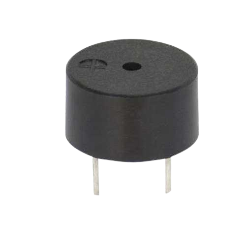
A buzzer is an audio signaling device that produces sound when an electric current passes through it. It is commonly used in applications where audible alerts or notifications are required. Buzzers are widely utilized in alarms, timers, electronic toys, and various consumer electronics. They are available in two main types: active buzzers, which generate sound when powered, and passive buzzers, which require an external signal to produce sound.
Explore Projects Built with BUZZER
Explore Projects Built with BUZZER
Technical Specifications
Below are the general technical specifications for a typical buzzer. Note that specific values may vary depending on the manufacturer and model.
General Specifications
- Operating Voltage: 3V to 12V (commonly 5V)
- Current Consumption: 10mA to 50mA
- Sound Frequency: 2kHz to 4kHz (typical)
- Sound Pressure Level (SPL): 85dB to 100dB at 10cm
- Type: Active or Passive
- Operating Temperature: -20°C to 70°C
Pin Configuration and Descriptions
The buzzer typically has two pins, as described in the table below:
| Pin Name | Description |
|---|---|
| Positive (+) | Connect to the positive terminal of the power supply or signal source. |
| Negative (-) | Connect to the ground (GND) of the circuit. |
For active buzzers, simply applying a DC voltage to the pins will produce sound. For passive buzzers, an oscillating signal (e.g., PWM) is required to generate sound.
Usage Instructions
How to Use the Buzzer in a Circuit
- Identify the Type of Buzzer: Determine whether the buzzer is active or passive. Active buzzers are easier to use as they only require a DC voltage, while passive buzzers need a signal source.
- Connect the Pins:
- Connect the positive pin of the buzzer to the power supply or signal source.
- Connect the negative pin to the ground (GND) of the circuit.
- Power the Buzzer:
- For an active buzzer, apply the appropriate DC voltage (e.g., 5V) to produce sound.
- For a passive buzzer, generate a PWM signal using a microcontroller (e.g., Arduino) to produce sound.
Important Considerations and Best Practices
- Voltage Compatibility: Ensure the operating voltage of the buzzer matches the power supply in your circuit.
- Current Limiting: If necessary, use a resistor to limit the current to the buzzer.
- Signal Frequency: For passive buzzers, use a signal frequency within the buzzer's specified range (e.g., 2kHz to 4kHz) to achieve optimal sound output.
- Polarity: Always connect the positive and negative pins correctly to avoid damage to the buzzer.
Example: Connecting a Passive Buzzer to an Arduino UNO
Below is an example of how to connect and control a passive buzzer using an Arduino UNO:
Circuit Diagram
- Connect the positive pin of the buzzer to Arduino pin 9.
- Connect the negative pin of the buzzer to GND.
Code Example
// Example code to generate sound using a passive buzzer with Arduino UNO

int buzzerPin = 9; // Pin connected to the buzzer

void setup() {
  pinMode(buzzerPin, OUTPUT); // Set the buzzer pin as an output
}

void loop() {
  tone(buzzerPin, 2000); // Generate a 2kHz tone
  delay(1000);           // Wait for 1 second
  noTone(buzzerPin);     // Stop the tone
  delay(1000);           // Wait for 1 second
}
Explanation of the Code
- The
tone()function generates a square wave at the specified frequency (2kHz in this case) on the buzzer pin. - The
noTone()function stops the sound. - The
delay()function is used to alternate between sound and silence.
Troubleshooting and FAQs
Common Issues and Solutions
No Sound from the Buzzer:
- Cause: Incorrect wiring or insufficient voltage.
- Solution: Verify the connections and ensure the power supply matches the buzzer's operating voltage.
Low or Distorted Sound:
- Cause: Insufficient current or incorrect signal frequency (for passive buzzers).
- Solution: Check the power supply and ensure the signal frequency is within the buzzer's specified range.
Buzzer Overheats:
- Cause: Excessive voltage or current.
- Solution: Use a resistor to limit the current and ensure the voltage is within the specified range.
Buzzer Does Not Respond to PWM Signal:
- Cause: Incorrect signal frequency or damaged buzzer.
- Solution: Verify the signal frequency and test the buzzer with a known working circuit.
FAQs
Can I use a passive buzzer without a microcontroller?
- Yes, you can use an external oscillator circuit to generate the required signal for a passive buzzer.
What is the difference between an active and a passive buzzer?
- An active buzzer has a built-in oscillator and produces sound when powered with DC voltage. A passive buzzer requires an external signal source to generate sound.
Can I control the volume of the buzzer?
- The volume is generally fixed, but you can reduce it by lowering the supply voltage (within the operating range).
Is it safe to connect a buzzer directly to an Arduino pin?
- Yes, for most buzzers, it is safe as long as the current draw is within the Arduino pin's limit (40mA max). However, using a current-limiting resistor is recommended for added safety.