How to Use 12v ISOLATOR: Examples, Pinouts, and Specs
12V Isolator Documentation
1. Introduction
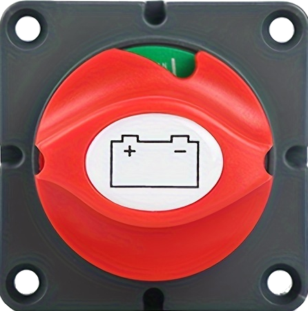
The 12V Isolator is an essential electronic component designed to disconnect the power supply in a 12V electrical system. It ensures safety by isolating the power source, preventing battery drain, and protecting connected devices when the system is not in use. This component is widely used in automotive, marine, and solar power systems where maintaining battery health and ensuring electrical safety are critical.
Common Applications:
- Automotive Systems: Prevents car batteries from draining when the vehicle is off.
- Marine Systems: Isolates power in boats to protect batteries and onboard electronics.
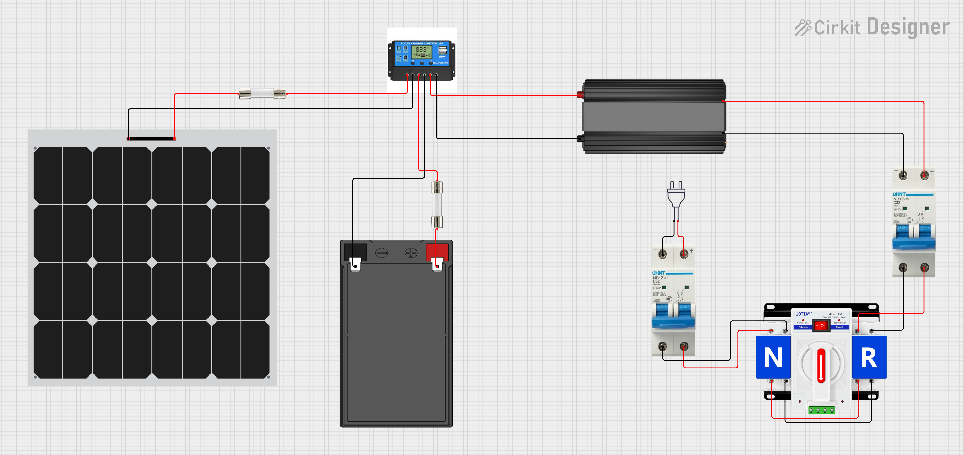
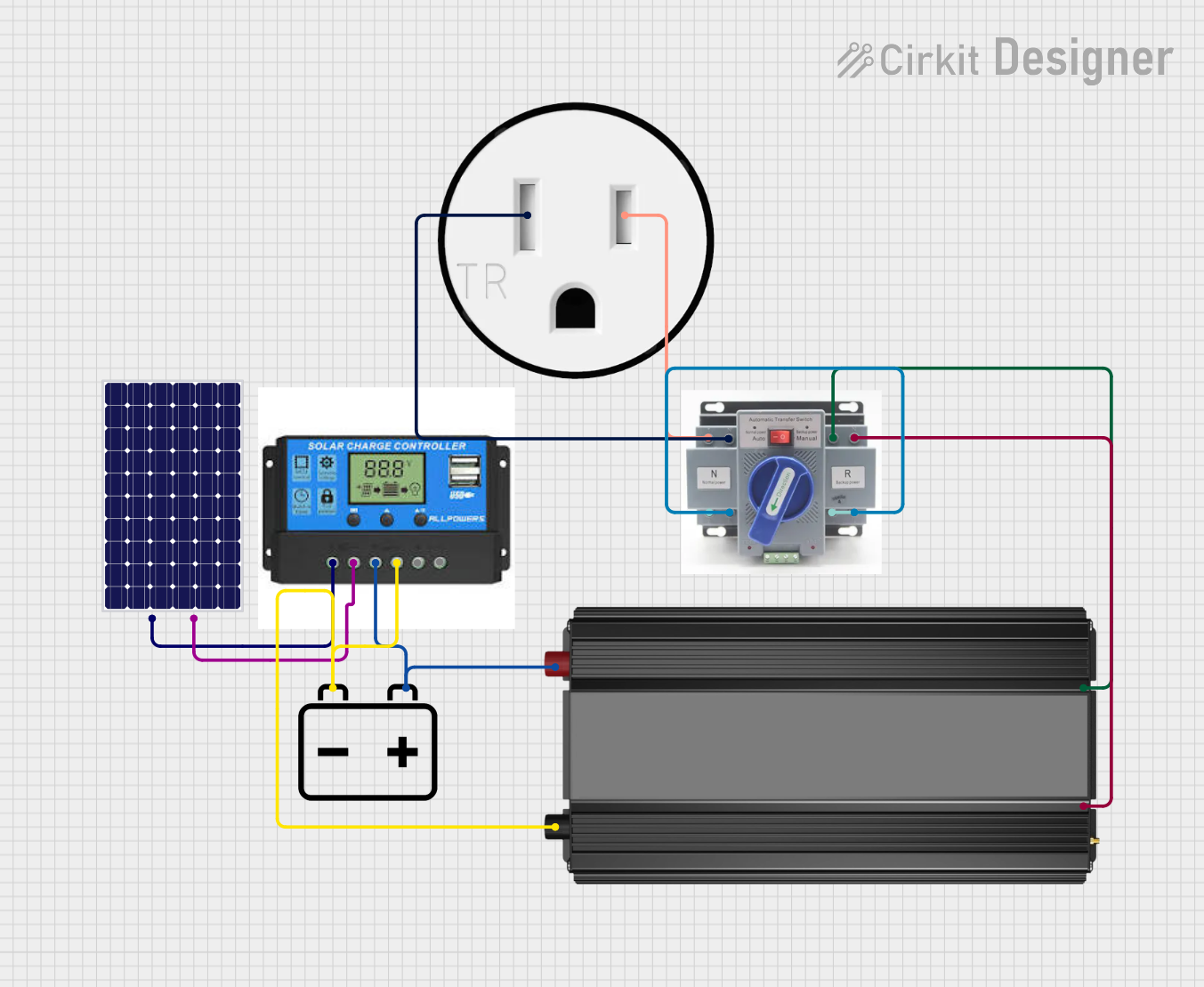
- Solar Power Systems: Disconnects batteries from solar panels during maintenance or inactivity.
- Backup Power Systems: Ensures safe disconnection of batteries in UPS or backup systems.
2. Technical Specifications
The following table outlines the key technical details of the 12V Isolator:
| Parameter | Value |
|---|---|
| Operating Voltage | 12V DC |
| Maximum Current Rating | 100A |
| Isolation Type | Electrical (Relay-based or Solid-State) |
| Power Consumption | < 1W |
| Operating Temperature | -40°C to +85°C |
| Dimensions | 60mm x 40mm x 30mm |
| Mounting Type | Screw or Panel Mount |
Pin Configuration and Descriptions
| Pin Name | Description |
|---|---|
| Input (+) | Positive terminal for the 12V power source. |
| Input (-) | Negative terminal for the 12V power source. |
| Output (+) | Positive terminal for the load connection. |
| Output (-) | Negative terminal for the load connection. |
| Control Pin | Optional pin to control the isolator (e.g., via microcontroller). |
3. Usage Instructions
How to Use the 12V Isolator in a Circuit:
Connect the Power Source:
- Attach the positive terminal of the 12V power source to the
Input (+)pin. - Attach the negative terminal of the 12V power source to the
Input (-)pin.
- Attach the positive terminal of the 12V power source to the
Connect the Load:
- Connect the positive terminal of the load (e.g., a motor, light, or battery) to the
Output (+)pin. - Connect the negative terminal of the load to the
Output (-)pin.
- Connect the positive terminal of the load (e.g., a motor, light, or battery) to the
Optional Control:
- If the isolator has a control pin, connect it to a microcontroller (e.g., Arduino UNO) or a manual switch to enable or disable the isolator.
Power On:
- Turn on the 12V power source. The isolator will allow current to flow to the load when activated.
Important Considerations:
- Ensure the isolator's current rating matches or exceeds the maximum current of your load.
- Use appropriate wire gauges to handle the current without overheating.
- If using the control pin with a microcontroller, ensure the control signal voltage matches the isolator's requirements.
- Mount the isolator securely to prevent vibrations or movement in automotive or marine applications.
4. Example Circuit with Arduino UNO
The 12V isolator can be controlled using an Arduino UNO to automate the disconnection of the power supply. Below is an example circuit and code:
Circuit Diagram:
- Connect the
Control Pinof the isolator to Arduino pin D7. - Connect the
Input (+)andInput (-)to a 12V power source. - Connect the
Output (+)andOutput (-)to the load (e.g., a 12V LED strip).
Arduino Code:
// 12V Isolator Control with Arduino UNO
// This code toggles the isolator on and off every 5 seconds.

#define ISOLATOR_PIN 7  // Define the Arduino pin connected to the isolator

void setup() {
  pinMode(ISOLATOR_PIN, OUTPUT);  // Set the isolator pin as an output
  digitalWrite(ISOLATOR_PIN, LOW);  // Start with the isolator off
}

void loop() {
  digitalWrite(ISOLATOR_PIN, HIGH);  // Turn the isolator on
  delay(5000);  // Wait for 5 seconds
  digitalWrite(ISOLATOR_PIN, LOW);  // Turn the isolator off
  delay(5000);  // Wait for 5 seconds
}
Notes:
- Ensure the isolator's control pin is compatible with the 5V logic level of the Arduino UNO.
- Use a flyback diode across the isolator's coil (if relay-based) to protect the Arduino from voltage spikes.
5. Troubleshooting and FAQs
Common Issues and Solutions:
| Issue | Possible Cause | Solution |
|---|---|---|
| Isolator does not activate. | Control pin not receiving signal. | Check the control pin connection and signal. |
| Load does not receive power. | Incorrect wiring or loose connections. | Verify all connections and polarity. |
| Isolator overheats during use. | Load current exceeds isolator rating. | Use an isolator with a higher current rating. |
| Arduino cannot control the isolator. | Voltage mismatch between Arduino and isolator. | Use a level shifter or compatible isolator. |
Frequently Asked Questions:
Can I use the 12V isolator with a 24V system?
- No, the isolator is designed specifically for 12V systems. Using it with higher voltages may damage the component.
Is the isolator waterproof?
- Most isolators are not waterproof. If used in marine or outdoor applications, ensure it is housed in a waterproof enclosure.
Can I control the isolator manually without a microcontroller?
- Yes, you can use a manual switch to control the isolator's control pin.
What type of loads can the isolator handle?
- The isolator can handle resistive (e.g., lights) and inductive (e.g., motors) loads, provided the current does not exceed its rating.
6. Conclusion
The 12V Isolator is a versatile and reliable component for managing power in 12V electrical systems. By following the guidelines in this documentation, users can safely and effectively integrate the isolator into their projects, ensuring optimal performance and protection for their devices. Whether you're working on an automotive, marine, or solar power system, the 12V isolator is an indispensable tool for maintaining safety and efficiency.
Explore Projects Built with 12v ISOLATOR


Explore Projects Built with 12v ISOLATOR