
How to Use Adafruit I2C Quad Rotary Encoder Breakout: Examples, Pinouts, and Specs
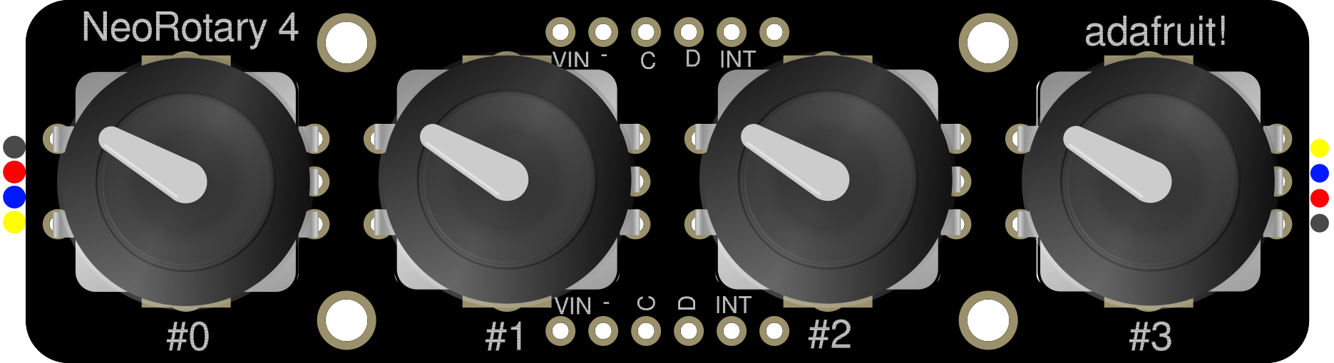
 Design with Adafruit I2C Quad Rotary Encoder Breakout in Cirkit Designer
Introduction
The Adafruit I2C Quad Rotary Encoder Breakout (Manufacturer Part ID: 5752) is a versatile breakout board designed to simplify the integration of up to four rotary encoders into your project. It communicates via the I2C protocol, reducing the number of GPIO pins required and enabling precise control and input for various applications. This breakout board is ideal for projects involving user interfaces, menu navigation, volume control, and other applications requiring rotary input.
Explore Projects Built with Adafruit I2C Quad Rotary Encoder Breakout
 Open Project in Cirkit Designer
 Open Project in Cirkit Designer
 Open Project in Cirkit Designer
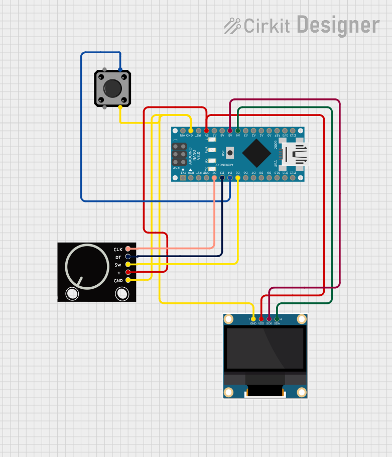 Open Project in Cirkit Designer
Explore Projects Built with Adafruit I2C Quad Rotary Encoder Breakout
Open Project in Cirkit DesignerOpen Project in Cirkit DesignerOpen Project in Cirkit DesignerOpen Project in Cirkit DesignerCommon Applications and Use Cases
- User interface controls for embedded systems
- Volume and parameter adjustment in audio devices
- Menu navigation in graphical or text-based displays
- Robotics and automation systems requiring precise input
- Gaming controllers and custom input devices
Technical Specifications
The Adafruit I2C Quad Rotary Encoder Breakout is built for ease of use and flexibility. Below are its key technical details:
Key Technical Details
| Parameter | Value |
|---|---|
| Operating Voltage | 3.3V or 5V |
| Communication Protocol | I2C |
| Default I2C Address | 0x36 (configurable via jumpers) |
| Number of Encoders | Up to 4 |
| Encoder Type Supported | Incremental (rotary) |
| Pull-up Resistors | Integrated |
| Dimensions | 25mm x 25mm x 4mm |
Pin Configuration and Descriptions
The breakout board has the following pin layout:
| Pin Name | Description |
|---|---|
| VIN | Power input (3.3V or 5V) |
| GND | Ground connection |
| SCL | I2C clock line |
| SDA | I2C data line |
| A1, B1 | Encoder 1 signal pins (A and B channels) |
| A2, B2 | Encoder 2 signal pins (A and B channels) |
| A3, B3 | Encoder 3 signal pins (A and B channels) |
| A4, B4 | Encoder 4 signal pins (A and B channels) |
Usage Instructions
How to Use the Component in a Circuit
- Power the Board: Connect the VIN pin to a 3.3V or 5V power source and the GND pin to ground.
- Connect I2C Lines: Connect the SCL and SDA pins to the corresponding I2C pins on your microcontroller (e.g., Arduino UNO).
- Attach Rotary Encoders: Connect the A and B signal pins of your rotary encoders to the corresponding A1/B1, A2/B2, etc., pins on the breakout board.
- Set the I2C Address: If using multiple boards, configure unique I2C addresses by adjusting the solder jumpers on the back of the board.
- Install Required Libraries: Use the Adafruit
Adafruit_seesawlibrary to interface with the board.
Important Considerations and Best Practices
- Ensure that the I2C pull-up resistors are enabled if your microcontroller does not have them.
- Use shielded cables for longer connections to minimize noise interference.
- Avoid exceeding the maximum voltage rating of the board (5V).
- If using multiple boards, ensure each has a unique I2C address to avoid conflicts.
Example Code for Arduino UNO
Below is an example of how to use the Adafruit I2C Quad Rotary Encoder Breakout with an Arduino UNO:
#include <Wire.h>
#include "Adafruit_seesaw.h"

// Create a seesaw object for the breakout board
Adafruit_seesaw ss;

void setup() {
  Serial.begin(115200); // Initialize serial communication for debugging
  while (!Serial) delay(10); // Wait for Serial to initialize

  // Initialize the seesaw board
  if (!ss.begin(0x36)) { // Default I2C address is 0x36
    Serial.println("Failed to find seesaw device! Check wiring.");
    while (1);
  }
  Serial.println("Seesaw device found!");

  // Configure the rotary encoder pins
  ss.pinMode(24, INPUT_PULLUP); // Encoder 1 A pin
  ss.pinMode(25, INPUT_PULLUP); // Encoder 1 B pin
}

void loop() {
  // Read encoder position (example for Encoder 1)
  int32_t encoderPosition = ss.getEncoderPosition(0); // Encoder 0 corresponds to A1/B1
  Serial.print("Encoder 1 Position: ");
  Serial.println(encoderPosition);

  delay(100); // Small delay to avoid flooding the serial monitor
}
Notes:
- Install the
Adafruit_seesawlibrary via the Arduino Library Manager before running the code. - Modify the I2C address in the
ss.begin()function if you have changed the default address.
Troubleshooting and FAQs
Common Issues and Solutions
The board is not detected on the I2C bus.
- Ensure the VIN and GND pins are properly connected to the power supply.
- Verify the SCL and SDA connections to the microcontroller.
- Check for conflicting I2C addresses if multiple devices are connected.
Rotary encoder readings are inconsistent or incorrect.
- Ensure the encoder signal pins (A and B) are securely connected to the breakout board.
- Verify that the encoders are incremental and compatible with the board.
Multiple boards are not working together.
- Ensure each board has a unique I2C address by adjusting the solder jumpers.
FAQs
Q: Can I use fewer than four rotary encoders?
A: Yes, you can use as few as one encoder. Simply connect the encoder to the desired pins and leave the others unconnected.
Q: What is the maximum cable length for the I2C connection?
A: The maximum length depends on the pull-up resistor values and the operating frequency. For standard 100kHz I2C, lengths up to 1 meter are typically reliable.
Q: Can I use this board with a Raspberry Pi?
A: Yes, the board is compatible with any device that supports I2C communication, including Raspberry Pi. Use the appropriate libraries for your platform.
Q: How do I change the I2C address?
A: Adjust the solder jumpers on the back of the board to set a new address. Refer to the Adafruit documentation for the address mapping.
This concludes the documentation for the Adafruit I2C Quad Rotary Encoder Breakout.