How to Use Adafruit EYESPI Breakout Board: Examples, Pinouts, and Specs
Introduction
The Adafruit EYESPI Breakout Board is a versatile and compact breakout board designed to simplify the connection of displays using the EYESPI interface. This board provides a standardized way to connect microcontrollers, such as Arduino, Raspberry Pi, or other development boards, to displays with minimal wiring and effort. It is particularly useful for projects requiring high-speed SPI communication with displays.
Explore Projects Built with Adafruit EYESPI Breakout Board
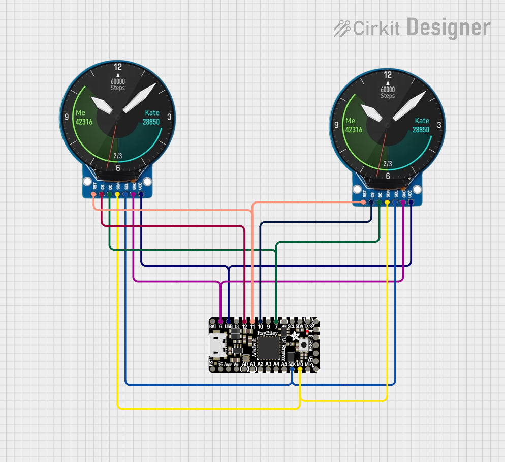

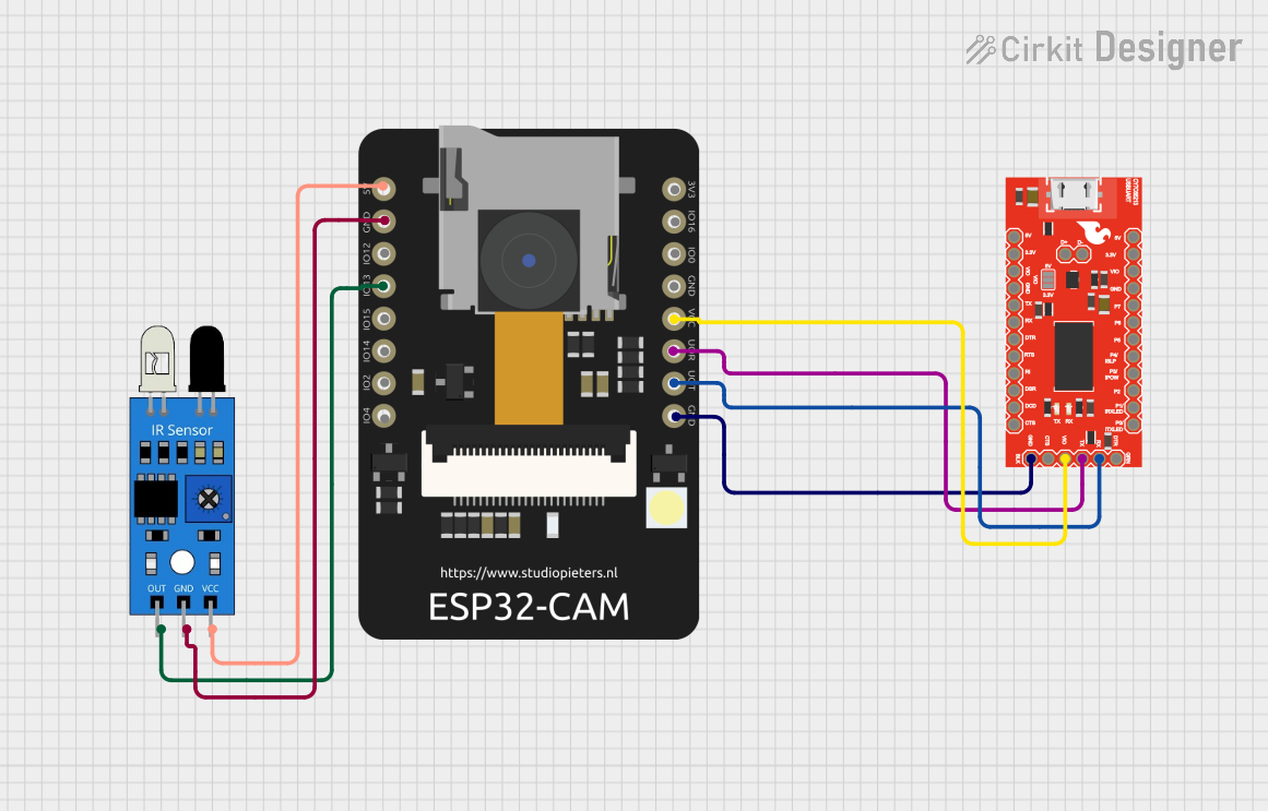
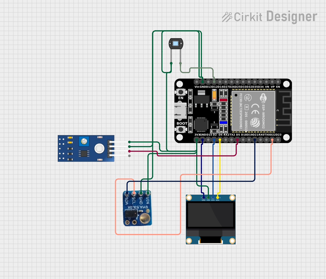
Explore Projects Built with Adafruit EYESPI Breakout Board
Common Applications and Use Cases
- Connecting microcontrollers to high-resolution displays
- Prototyping display-based projects
- Simplifying wiring for SPI-based display modules
- Applications in IoT, robotics, and embedded systems requiring graphical interfaces
Technical Specifications
The Adafruit EYESPI Breakout Board is designed to work seamlessly with the EYESPI interface and supports a wide range of display modules. Below are the key technical details:
Key Specifications
| Parameter | Value |
|---|---|
| Manufacturer | Adafruit |
| Part Number | Adafruit EYESPI Breakout Board |
| Interface Type | EYESPI (Extended SPI) |
| Voltage Range | 3.3V to 5V |
| Supported Protocol | SPI |
| Dimensions | 25mm x 25mm |
| Mounting Style | PCB Mount |
| Connector Type | 18-pin FPC connector |
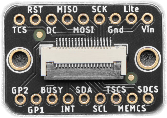
Pin Configuration and Descriptions
The breakout board features an 18-pin FPC connector for interfacing with displays. Below is the pinout description:
| Pin Number | Pin Name | Description |
|---|---|---|
| 1 | 3.3V | 3.3V power supply input |
| 2 | 5V | 5V power supply input |
| 3 | GND | Ground |
| 4 | SCK | SPI Clock |
| 5 | MOSI | SPI Master Out Slave In |
| 6 | MISO | SPI Master In Slave Out |
| 7 | CS | Chip Select |
| 8 | DC | Data/Command Control |
| 9 | RST | Reset |
| 10 | INT | Interrupt (optional, for advanced use) |
| 11-18 | NC | Not Connected (reserved for future use) |
Usage Instructions
The Adafruit EYESPI Breakout Board is straightforward to use and can be integrated into a variety of projects. Below are the steps and best practices for using the board:
How to Use the Component in a Circuit
- Power Supply: Connect the 3.3V or 5V pin to the appropriate power source. Ensure the voltage matches the requirements of your display module.
- SPI Connections: Connect the SCK, MOSI, MISO, and CS pins to the corresponding SPI pins on your microcontroller.
- Control Pins: Connect the DC and RST pins to GPIO pins on your microcontroller for display control.
- Interrupt Pin (Optional): Use the INT pin if your display module supports interrupt-driven communication.
- Connect the Display: Attach the display module to the 18-pin FPC connector on the breakout board.
- Programming: Use the appropriate library (e.g., Adafruit GFX or Adafruit ST7735/ST7789) to control the display.
Important Considerations and Best Practices
- Ensure the power supply voltage matches the requirements of both the breakout board and the connected display.
- Use short and properly routed wires to minimize noise in SPI communication.
- If using an Arduino UNO, note that the SPI pins are located on the ICSP header.
- Always double-check the pin connections to avoid damaging the breakout board or the display.
Example Code for Arduino UNO
Below is an example of how to use the Adafruit EYESPI Breakout Board with an Arduino UNO and a compatible display:
#include <Adafruit_GFX.h>       // Core graphics library
#include <Adafruit_ST7735.h>    // Library for ST7735/ST7789 displays

// Define SPI pins for Arduino UNO
#define TFT_CS   10  // Chip Select pin
#define TFT_RST  9   // Reset pin
#define TFT_DC   8   // Data/Command pin

// Initialize the display object
Adafruit_ST7735 tft = Adafruit_ST7735(TFT_CS, TFT_DC, TFT_RST);

void setup() {
  // Initialize serial communication for debugging
  Serial.begin(9600);
  Serial.println("Initializing display...");

  // Initialize the display
  tft.initR(INITR_BLACKTAB);  // Use appropriate initialization for your display
  tft.fillScreen(ST77XX_BLACK);  // Clear the screen with black color
  tft.setTextColor(ST77XX_WHITE);
  tft.setTextSize(2);
  tft.setCursor(0, 0);
  tft.println("Hello, EYESPI!");
}

void loop() {
  // Add your display logic here
}
Troubleshooting and FAQs
Common Issues Users Might Face
Display Not Turning On:
- Verify the power supply voltage and connections.
- Ensure the display is properly seated in the FPC connector.
No Output on Display:
- Check the SPI connections (SCK, MOSI, MISO, CS).
- Ensure the correct library and initialization code are used for your display.
Flickering or Noise on Display:
- Use shorter wires for SPI connections.
- Add decoupling capacitors near the power pins if necessary.
Microcontroller Not Responding:
- Ensure the INT pin is not floating if used.
- Check for conflicting pin assignments in your code.
Solutions and Tips for Troubleshooting
- Use a multimeter to verify continuity and voltage levels on all connections.
- Refer to the datasheet or user manual of your specific display module for additional configuration details.
- Update your libraries to the latest versions to ensure compatibility.
By following this documentation, you can effectively integrate the Adafruit EYESPI Breakout Board into your projects and troubleshoot any issues that arise.