How to Use Myoware Shield: Examples, Pinouts, and Specs
Introduction
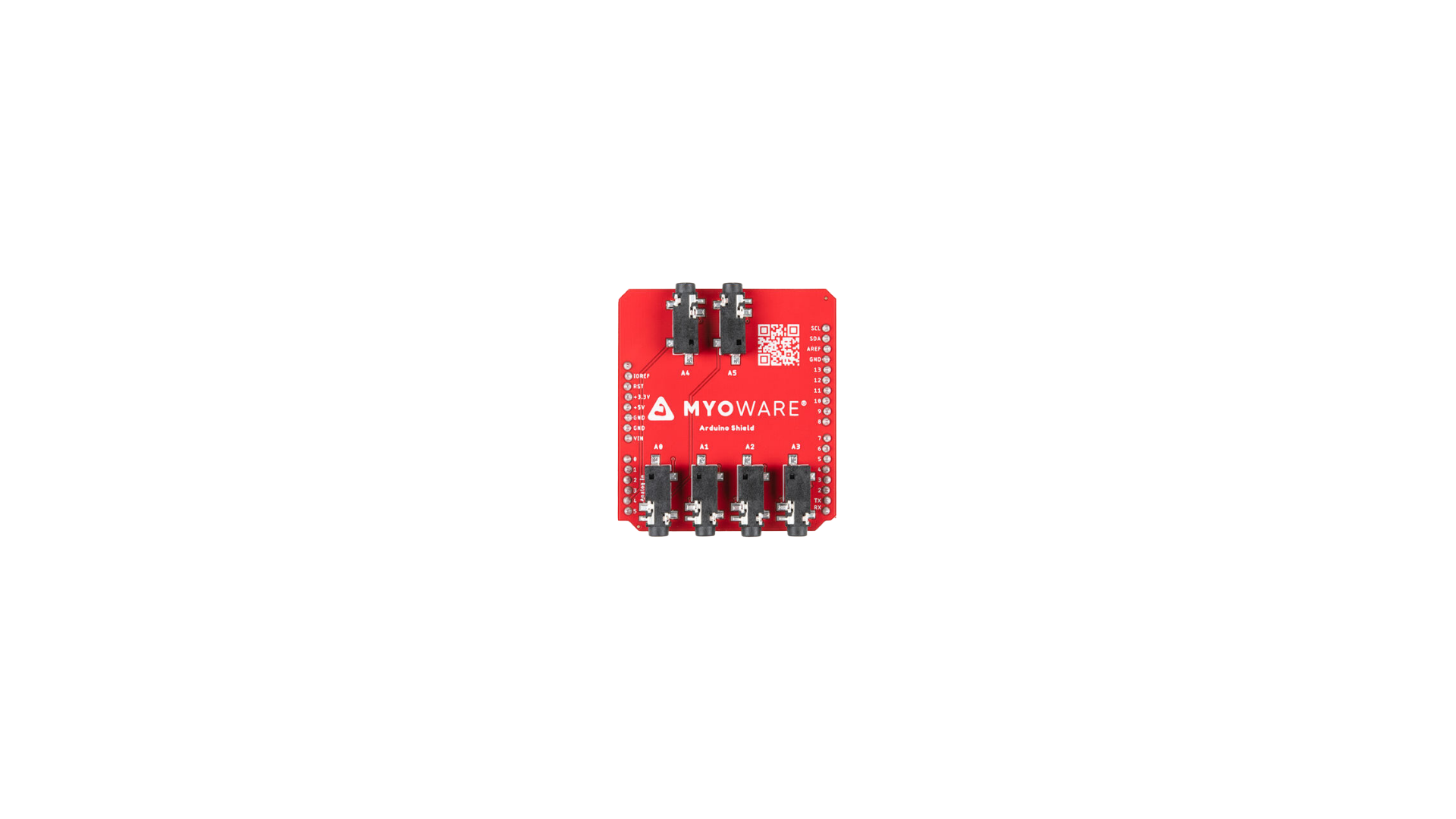
The Myoware Shield is a muscle sensor shield designed by Myoware for use with Arduino boards. It detects the electrical signals generated by muscle contractions (electromyography or EMG) and converts them into a readable signal for microcontrollers. This shield enables the development of biofeedback systems, prosthetics, robotics, and other control applications that respond to muscle activity.
Explore Projects Built with Myoware Shield
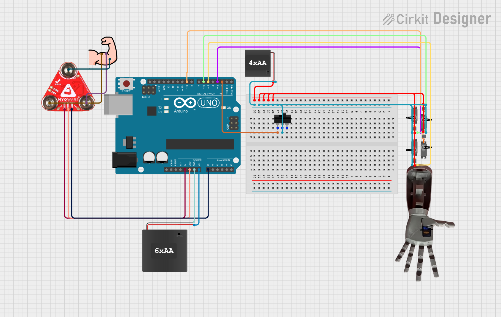
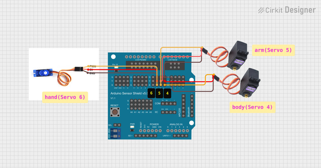
Explore Projects Built with Myoware Shield
Common Applications and Use Cases
- Prosthetic limb control
- Robotics and human-machine interfaces
- Biofeedback systems for rehabilitation
- Gaming and virtual reality (VR) control
- Wearable technology and fitness tracking
Technical Specifications
The Myoware Shield is designed to interface seamlessly with Arduino boards and other microcontrollers. Below are its key technical details:
Key Technical Details
- Operating Voltage: 3.3V to 5V
- Output Signal: 0V to Vcc (analog signal proportional to muscle activity)
- Input Impedance: >1MΩ
- Electrode Connector: Snap-style connectors for standard EMG electrodes
- Dimensions: 1.5" x 1.0" (38mm x 25mm)
- Weight: ~5g (without electrodes)
Pin Configuration and Descriptions
The Myoware Shield has a simple pinout for easy integration with Arduino boards. Below is the pin configuration:
| Pin | Name | Description |
|---|---|---|
| 1 | VCC | Power supply input (3.3V or 5V). Connect to the Arduino's 3.3V or 5V pin. |
| 2 | GND | Ground connection. Connect to the Arduino's GND pin. |
| 3 | SIG | Analog output signal. Provides a voltage proportional to muscle activity. |
| 4 | RAW | Raw EMG signal output (optional, for advanced users). |
| 5 | REF | Reference voltage input (optional, for advanced configurations). |
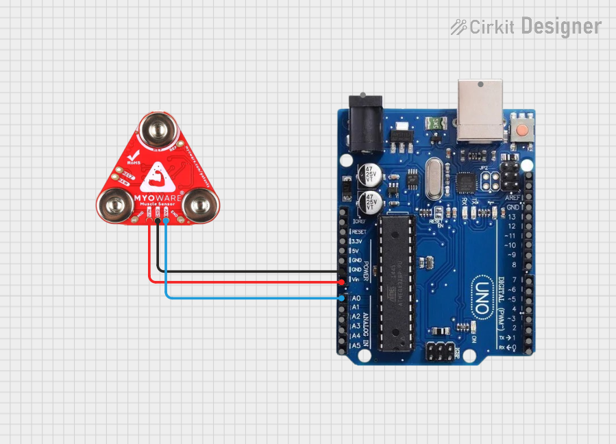
Usage Instructions
How to Use the Myoware Shield in a Circuit
Connect the Shield to an Arduino:
- Attach the Myoware Shield to your Arduino board using jumper wires or a breadboard.
- Connect the
VCCpin to the Arduino's 3.3V or 5V pin. - Connect the
GNDpin to the Arduino's GND pin. - Connect the
SIGpin to one of the Arduino's analog input pins (e.g., A0).
Attach Electrodes:
- Snap three standard EMG electrodes onto the Myoware Shield's connectors.
- Place the electrodes on the target muscle group as follows:
- Two electrodes on the muscle belly (parallel to the muscle fibers).
- One electrode on a bony or inactive area as a reference (ground).
Read the Signal:
- Use the Arduino's analog input to read the signal from the
SIGpin. - The signal will range from 0V to Vcc, where higher values indicate stronger muscle activity.
- Use the Arduino's analog input to read the signal from the
Important Considerations and Best Practices
- Electrode Placement: Proper placement of electrodes is critical for accurate readings. Ensure the skin is clean and free of oils before applying electrodes.
- Signal Filtering: The Myoware Shield includes onboard filtering, but additional software filtering may improve signal quality.
- Power Supply: Use a stable power source to minimize noise in the signal.
- Avoid Interference: Keep the shield and electrodes away from sources of electrical noise, such as motors or high-frequency devices.
Example Arduino Code
Below is an example Arduino sketch to read and display the muscle activity signal from the Myoware Shield:
// Myoware Shield Example Code
// This code reads the analog signal from the Myoware Shield and displays it
// on the Serial Monitor. Connect the SIG pin to Arduino analog pin A0.

const int myowarePin = A0; // Analog pin connected to the SIG pin of Myoware Shield

void setup() {
  Serial.begin(9600); // Initialize serial communication at 9600 baud
  pinMode(myowarePin, INPUT); // Set the Myoware pin as an input
}

void loop() {
  int muscleSignal = analogRead(myowarePin); // Read the analog signal
  Serial.print("Muscle Signal: ");
  Serial.println(muscleSignal); // Print the signal value to the Serial Monitor
  delay(100); // Delay for 100ms to reduce data output frequency
}
Troubleshooting and FAQs
Common Issues and Solutions
No Signal or Weak Signal:
- Cause: Poor electrode placement or loose connections.
- Solution: Ensure the electrodes are properly placed on the muscle and securely connected to the shield.
Noisy or Erratic Signal:
- Cause: Electrical interference or poor skin contact.
- Solution: Move the setup away from sources of interference and clean the skin before applying electrodes.
Signal Saturation (Always High):
- Cause: Incorrect power supply voltage or faulty shield.
- Solution: Verify the power supply voltage and check for any visible damage to the shield.
Arduino Not Reading Signal:
- Cause: Incorrect wiring or code issues.
- Solution: Double-check the wiring and ensure the correct analog pin is specified in the code.
FAQs
Q: Can I use the Myoware Shield with microcontrollers other than Arduino?
A: Yes, the Myoware Shield can be used with any microcontroller that supports analog input and operates at 3.3V or 5V.
Q: How long do the electrodes last?
A: The lifespan of the electrodes depends on usage and storage conditions. Replace them when adhesion weakens or signal quality degrades.
Q: Can I use the RAW pin for advanced applications?
A: Yes, the RAW pin provides the unfiltered EMG signal, which can be used for custom signal processing or advanced applications.
Q: Is the Myoware Shield safe to use?
A: Yes, the Myoware Shield is designed for safe, non-invasive use. However, it is not a medical device and should not be used for diagnostic purposes.