How to Use 74HC10: Examples, Pinouts, and Specs

Introduction
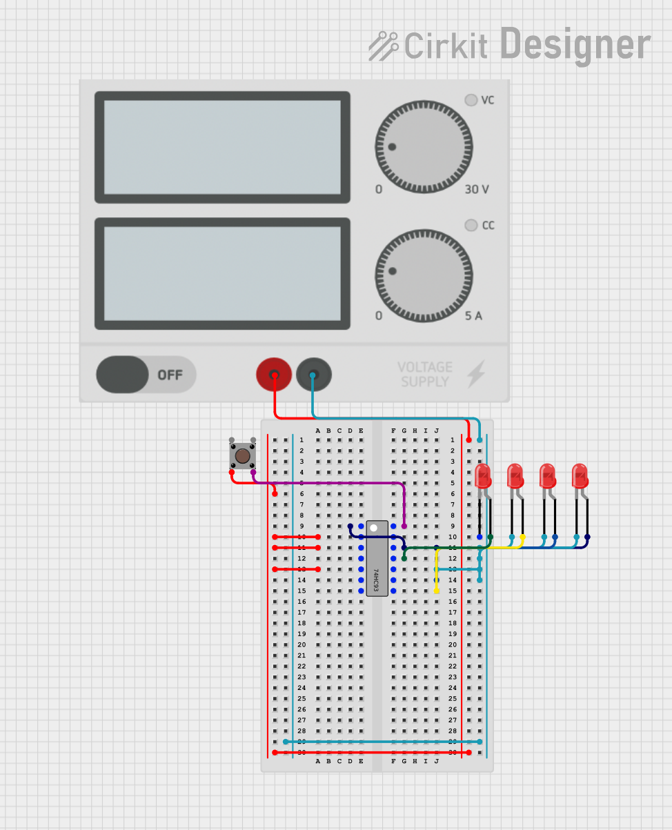
The 74HC10 is a high-speed CMOS device that contains three independent 3-input NAND gates. This integrated circuit (IC) is widely used in digital electronics for combining signals and implementing logic functions. The NAND gate is a fundamental building block in digital circuits, and its versatility makes the 74HC10 suitable for a variety of applications, including logic gate functions, signal gating, and building more complex logic structures such as multiplexers, decoders, and arithmetic logic units.
Explore Projects Built with 74HC10


Explore Projects Built with 74HC10
Technical Specifications
Key Technical Details
- Logic Type: NAND Gate
- Number of Gates: 3
- Number of Inputs per Gate: 3
- Supply Voltage (Vcc): 2V to 6V
- High-Level Input Voltage (VIH): Minimum 2V
- Low-Level Input Voltage (VIL): Maximum 0.8V
- Output Current (IO): ±5.2 mA
- Propagation Delay Time: 8ns (typical at Vcc = 5V)
- Operating Temperature Range: -40°C to +125°C
Pin Configuration and Descriptions
| Pin Number | Description |
|---|---|
| 1 | Input A1 |
| 2 | Input B1 |
| 3 | Input C1 |
| 4 | Output Y1 |
| 5 | Input A2 |
| 6 | Input B2 |
| 7 | Input C2 |
| 8 | Ground (GND) |
| 9 | Output Y2 |
| 10 | Input A3 |
| 11 | Input B3 |
| 12 | Input C3 |
| 13 | Output Y3 |
| 14 | Positive Supply (Vcc) |
Usage Instructions
How to Use the 74HC10 in a Circuit
Power Supply Connection: Connect pin 14 to the positive supply voltage (Vcc) within the range of 2V to 6V. Connect pin 8 to the ground (GND).
Input Connection: Apply the input signals to the A, B, and C inputs of the desired NAND gate. Ensure that the input voltage levels are compatible with the logic levels of the 74HC10.
Output Connection: The output of each NAND gate (Y) can be connected to other logic gates, microcontrollers, or any suitable load within the output current rating.
Decoupling Capacitor: It is good practice to place a 0.1 µF decoupling capacitor close to the Vcc pin to filter out noise and stabilize the power supply.
Important Considerations and Best Practices
Input Floating: Never leave the inputs of the NAND gates floating. Unused inputs should be tied to Vcc or GND to ensure predictable operation.
Output Loading: Do not exceed the maximum output current rating to avoid damaging the IC.
Signal Integrity: Keep the wiring short and use proper routing techniques to minimize crosstalk and signal degradation.
Static Discharge: The 74HC10 is CMOS technology and can be damaged by static discharge. Handle with appropriate anti-static precautions.
Troubleshooting and FAQs
Common Issues
Outputs Not Behaving as Expected: Ensure that all inputs are driven properly and not floating. Verify that the supply voltage is within the specified range.
IC Getting Hot: Check if the output is short-circuited or if there is an excessive load. Also, ensure that the supply voltage is not above the maximum rating.
Solutions and Tips for Troubleshooting
Verify Connections: Double-check the wiring against the pin configuration to ensure all connections are correct.
Measure Voltages: Use a multimeter to measure the supply voltage and the input/output levels to ensure they are within the specified range.
Replace IC: If the IC is suspected to be faulty after checking all connections and voltages, replace it with a new one.
FAQs
Q: Can I use the 74HC10 at a supply voltage lower than 2V? A: No, the 74HC10 is designed to operate within a supply voltage range of 2V to 6V.
Q: What happens if I exceed the maximum output current? A: Exceeding the maximum output current can lead to IC damage and failure.
Q: Can I connect the outputs of two NAND gates together? A: Directly connecting outputs can cause contention. Use proper logic design techniques to combine outputs.
Example Connection with Arduino UNO
The following example demonstrates how to connect a single NAND gate of the 74HC10 to an Arduino UNO and read the output state.
// Define the Arduino pin numbers for the inputs and output
const int inputA = 2;
const int inputB = 3;
const int inputC = 4;
const int outputY = 5;

void setup() {
  // Configure the input pins
  pinMode(inputA, OUTPUT);
  pinMode(inputB, OUTPUT);
  pinMode(inputC, OUTPUT);

  // Configure the output pin
  pinMode(outputY, INPUT);

  // Initialize serial communication
  Serial.begin(9600);
}

void loop() {
  // Set inputs to LOW (NAND gate will output HIGH)
  digitalWrite(inputA, LOW);
  digitalWrite(inputB, LOW);
  digitalWrite(inputC, LOW);

  // Read the output state
  int state = digitalRead(outputY);

  // Print the output state to the Serial Monitor
  Serial.print("Output state: ");
  Serial.println(state); // Expect 1 (HIGH) since all inputs are LOW

  // Wait for a second
  delay(1000);

  // Change one input to HIGH (NAND gate will output LOW)
  digitalWrite(inputA, HIGH);

  // Read the output state again
  state = digitalRead(outputY);

  // Print the new output state to the Serial Monitor
  Serial.print("Output state: ");
  Serial.println(state); // Expect 0 (LOW) since one input is HIGH

  // Wait for a second
  delay(1000);
}
This code sets up the Arduino to drive the inputs of one NAND gate on the 74HC10 and reads the output state. The Serial Monitor will display the output state, which changes based on the input conditions.