How to Use Piezoelectric Vibration Sensor Module:: Examples, Pinouts, and Specs
Introduction
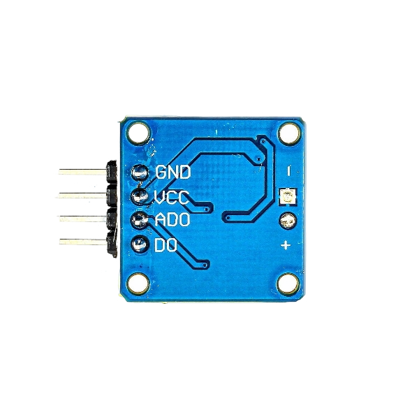
The Piezoelectric Vibration Sensor Module (Manufacturer: RoboticsBD, Part ID: RBD-2229) is a versatile sensor designed to detect vibrations and convert them into an electrical signal using the piezoelectric effect. This module is widely used in applications such as motion detection, vibration monitoring, and impact sensing. Its compact design and high sensitivity make it suitable for a variety of projects, including security systems, industrial equipment monitoring, and DIY electronics.
Explore Projects Built with Piezoelectric Vibration Sensor Module:
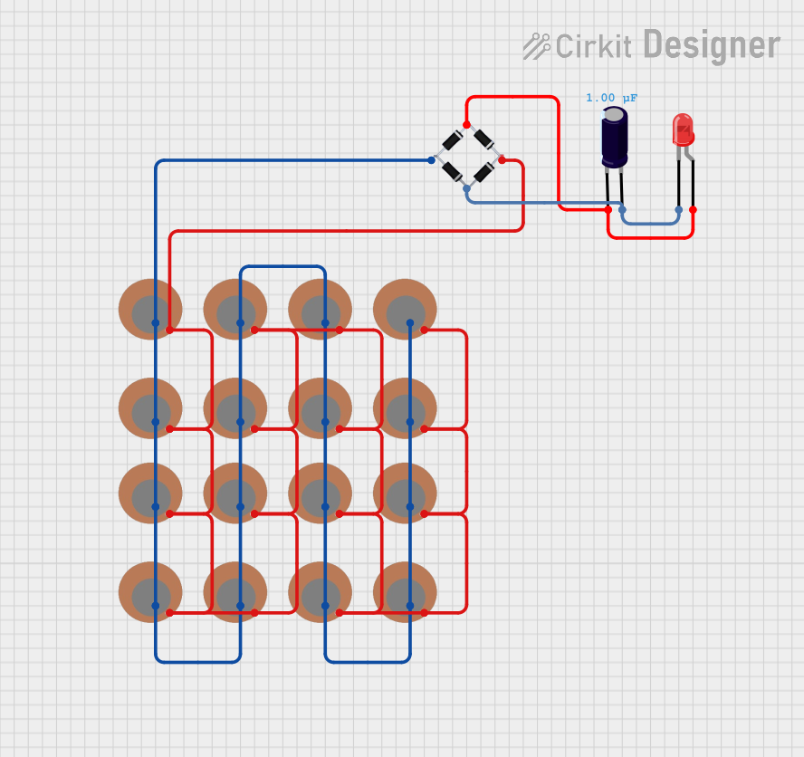

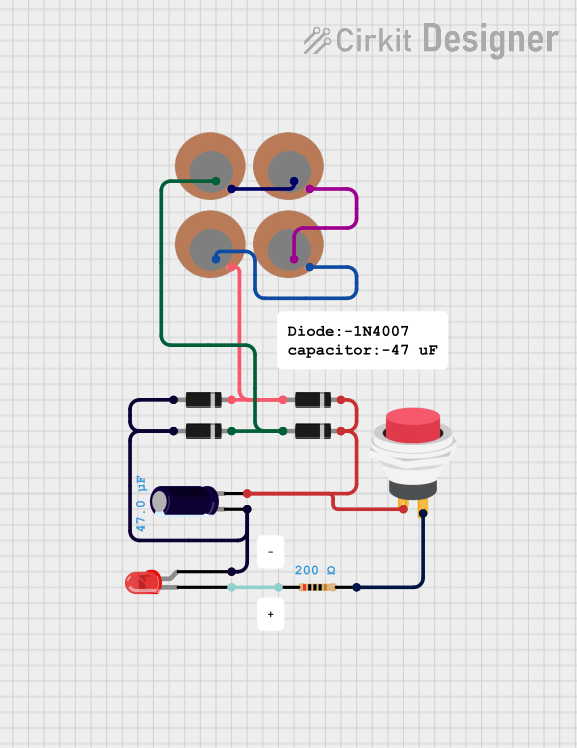
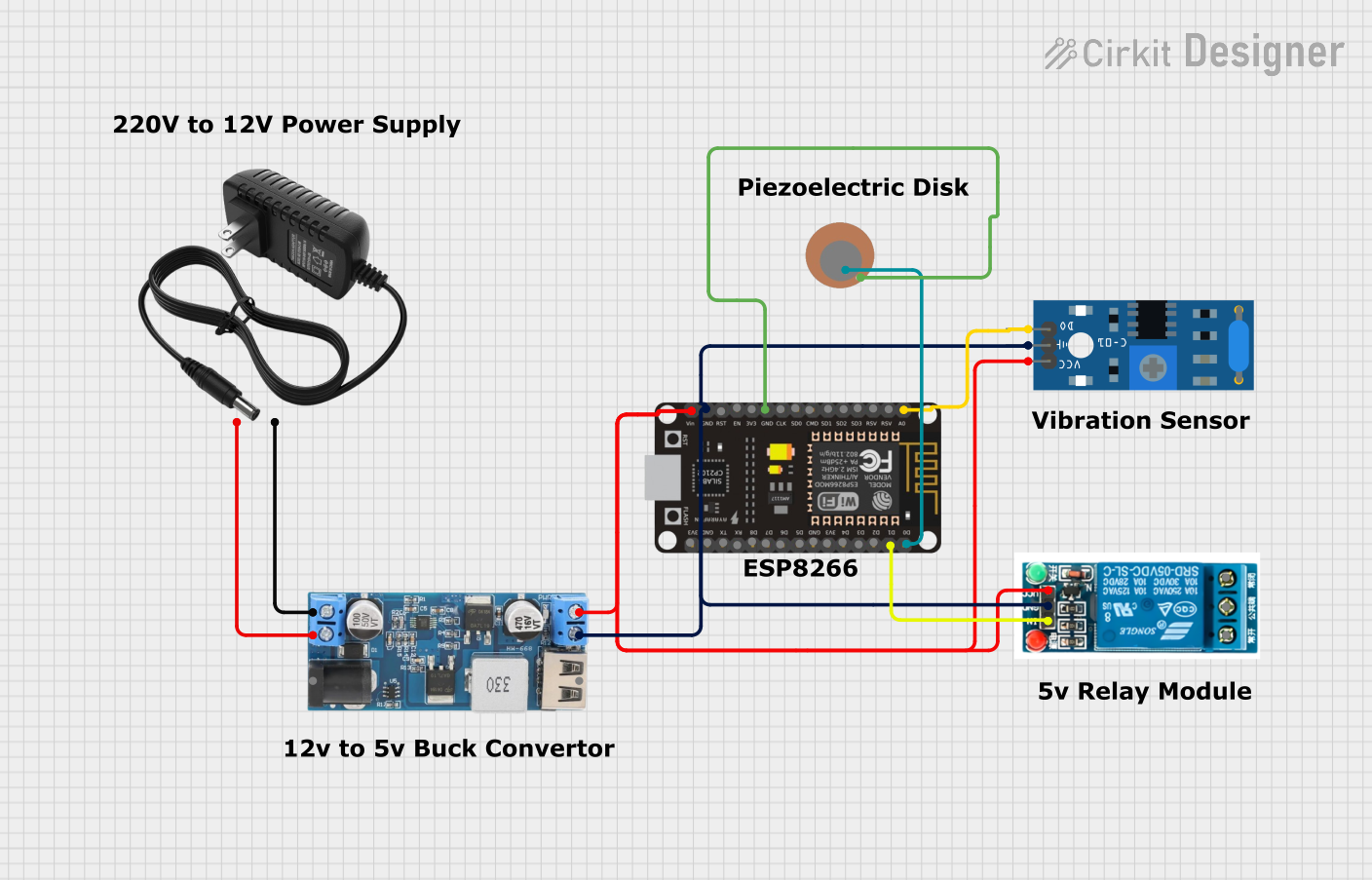
Explore Projects Built with Piezoelectric Vibration Sensor Module:
Common Applications
- Motion detection in security systems
- Monitoring vibrations in machinery or structures
- Impact detection in robotics and automation
- DIY projects requiring vibration sensing
Technical Specifications
Below are the key technical details of the Piezoelectric Vibration Sensor Module:
| Parameter | Value |
|---|---|
| Manufacturer | RoboticsBD |
| Part ID | RBD-2229 |
| Operating Voltage | 3.3V to 5V |
| Output Signal | Analog and Digital |
| Sensitivity | Adjustable via onboard potentiometer |
| Dimensions | 32mm x 15mm x 10mm |
| Operating Temperature | -20°C to 70°C |
| Weight | 5g |
Pin Configuration and Descriptions
The module has a 3-pin interface for easy integration into circuits:
| Pin | Name | Description |
|---|---|---|
| 1 | VCC | Power supply pin (3.3V to 5V) |
| 2 | GND | Ground connection |
| 3 | OUT | Output pin (provides analog or digital signal based on vibration) |
Usage Instructions
How to Use the Component in a Circuit
- Power the Module: Connect the
VCCpin to a 3.3V or 5V power source and theGNDpin to the ground of your circuit. - Connect the Output: Use the
OUTpin to read the sensor's output. This pin provides:- Analog Signal: Proportional to the intensity of the vibration.
- Digital Signal: High or low signal based on the vibration threshold set by the onboard potentiometer.
- Adjust Sensitivity: Use the onboard potentiometer to set the vibration threshold for the digital output.
Important Considerations and Best Practices
- Power Supply: Ensure a stable power supply to avoid noise in the output signal.
- Mounting: Secure the module firmly to prevent false readings caused by unintended vibrations.
- Signal Filtering: For applications requiring precise measurements, consider adding a capacitor to filter noise from the analog output.
- Arduino Compatibility: The module can be easily interfaced with an Arduino UNO for prototyping and testing.
Example: Connecting to an Arduino UNO
Below is an example of how to use the Piezoelectric Vibration Sensor Module with an Arduino UNO:
Circuit Connections
- Connect the
VCCpin of the module to the 5V pin on the Arduino. - Connect the
GNDpin of the module to the GND pin on the Arduino. - Connect the
OUTpin of the module to an analog input pin (e.g., A0) on the Arduino.
Arduino Code
// Piezoelectric Vibration Sensor Example with Arduino UNO
// Manufacturer: RoboticsBD, Part ID: RBD-2229

const int sensorPin = A0;  // Analog pin connected to the sensor's OUT pin
int sensorValue = 0;       // Variable to store the sensor reading

void setup() {
  Serial.begin(9600);      // Initialize serial communication at 9600 baud
  pinMode(sensorPin, INPUT); // Set the sensor pin as input
}

void loop() {
  sensorValue = analogRead(sensorPin); // Read the analog value from the sensor
  Serial.print("Vibration Level: ");
  Serial.println(sensorValue);        // Print the sensor value to the Serial Monitor

  delay(500); // Wait for 500ms before the next reading
}
Notes:
- The
sensorValuewill vary based on the intensity of the vibration detected. - You can modify the delay in the
loop()function to adjust the frequency of readings.
Troubleshooting and FAQs
Common Issues and Solutions
No Output Signal:
- Ensure the module is powered correctly (check
VCCandGNDconnections). - Verify that the onboard potentiometer is not set too high or too low.
- Ensure the module is powered correctly (check
False Readings:
- Check for loose connections or external vibrations affecting the module.
- Secure the module firmly to the surface to minimize noise.
Inconsistent Analog Output:
- Use a capacitor to filter noise from the analog signal.
- Ensure the power supply is stable and free from fluctuations.
Digital Output Not Triggering:
- Adjust the sensitivity using the onboard potentiometer.
- Verify that the vibration intensity exceeds the set threshold.
FAQs
Q1: Can this module detect very small vibrations?
A1: Yes, the module is highly sensitive, and the threshold can be adjusted using the potentiometer.
Q2: Is the module compatible with 3.3V microcontrollers like ESP32?
A2: Yes, the module operates within a voltage range of 3.3V to 5V, making it compatible with 3.3V systems.
Q3: Can I use this module outdoors?
A3: While the module operates in a wide temperature range, it is not waterproof. Use appropriate enclosures for outdoor applications.
Q4: How do I differentiate between analog and digital output?
A4: The analog output provides a continuous signal proportional to vibration intensity, while the digital output is a binary signal (high or low) based on the threshold set by the potentiometer.
By following this documentation, you can effectively integrate and utilize the Piezoelectric Vibration Sensor Module in your projects.