
How to Use fuse ATO: Examples, Pinouts, and Specs

 Design with fuse ATO in Cirkit Designer
Introduction
A Fuse ATO is a type of automotive fuse designed to provide overcurrent protection in electrical circuits. It is a blade-style fuse commonly used in vehicles and other low-voltage applications. The fuse operates by melting its internal element when the current exceeds a specified limit, effectively breaking the circuit and preventing damage to wiring, components, or devices.
Explore Projects Built with fuse ATO
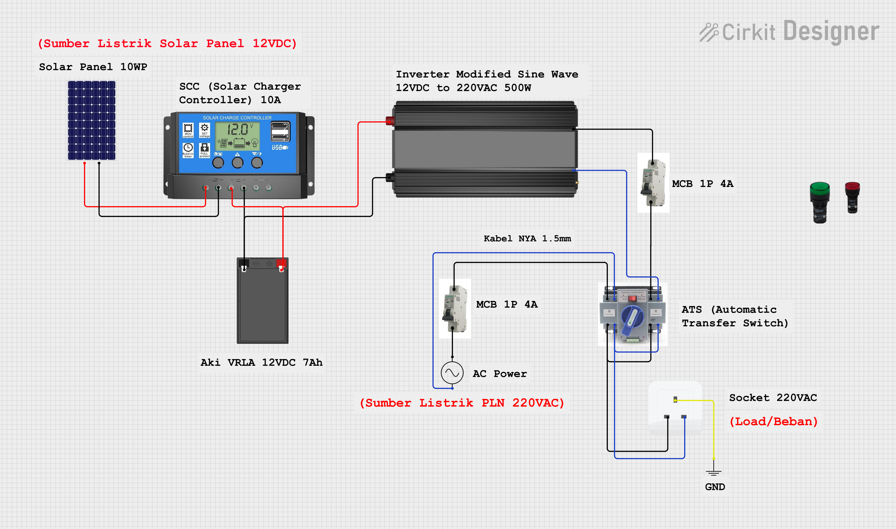 Open Project in Cirkit Designer
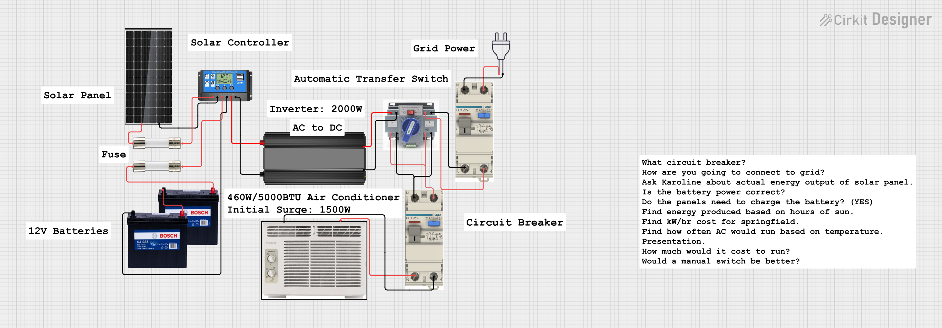 Open Project in Cirkit Designer
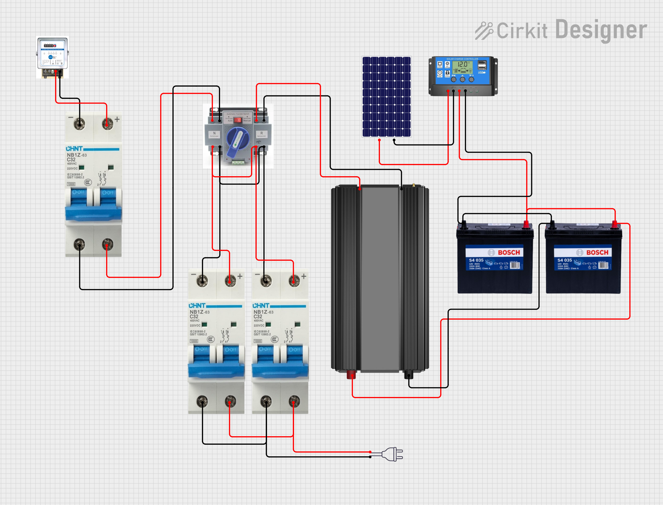 Open Project in Cirkit Designer
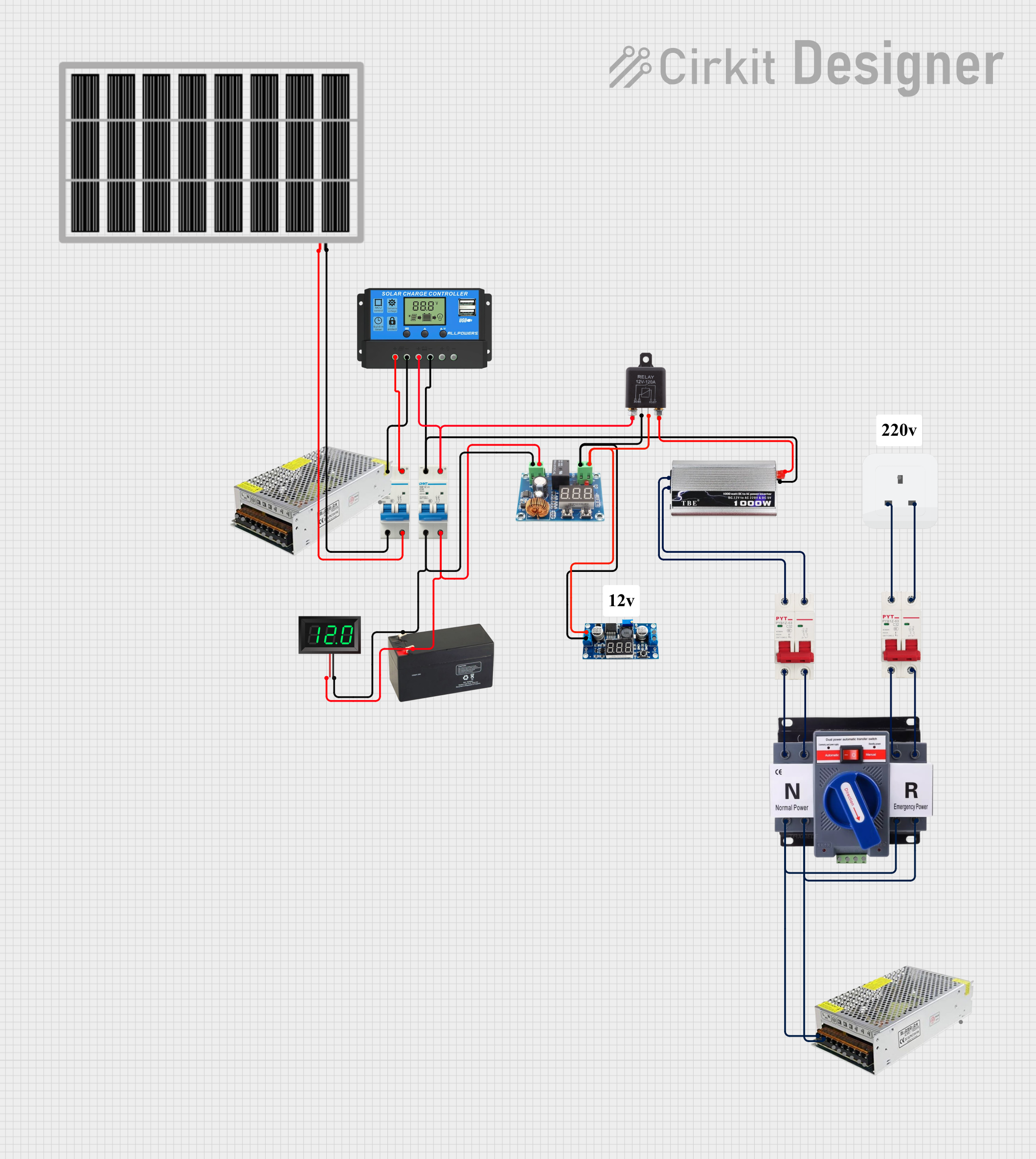 Open Project in Cirkit Designer
Explore Projects Built with fuse ATO
Open Project in Cirkit DesignerOpen Project in Cirkit DesignerOpen Project in Cirkit DesignerOpen Project in Cirkit DesignerCommon Applications and Use Cases
- Automotive electrical systems (e.g., cars, trucks, motorcycles)
- Low-voltage DC circuits in boats, RVs, and off-road vehicles
- Protection for auxiliary devices such as radios, lights, and chargers
- Industrial and hobbyist electronics requiring compact overcurrent protection
Technical Specifications
Below are the key technical details for a standard Fuse ATO:
| Parameter | Specification |
|---|---|
| Voltage Rating | 32V DC (typical) |
| Current Ratings | 1A to 40A (varies by fuse type) |
| Operating Temperature | -40°C to +125°C |
| Material | Plastic housing with zinc or copper blades |
| Dimensions | 19.1mm x 5.1mm x 18.5mm |
| Response Time | Fast-acting (varies by current rating) |
Pin Configuration and Descriptions
The Fuse ATO has two blade terminals that connect to the circuit. These terminals are designed to fit into standard automotive fuse holders.
| Pin | Description |
|---|---|
| Blade 1 | Connects to the positive side of the circuit |
| Blade 2 | Connects to the load side of the circuit |
Usage Instructions
How to Use the Fuse ATO in a Circuit
- Determine the Current Rating: Select a fuse with a current rating slightly higher than the normal operating current of the circuit. For example, if the circuit operates at 8A, use a 10A fuse.
- Insert into Fuse Holder: Place the Fuse ATO into a compatible fuse holder or fuse box. Ensure the blades are securely seated to maintain a proper connection.
- Connect the Circuit: Wire the fuse holder in series with the circuit to ensure the fuse protects the entire load.
- Test the Circuit: Power on the circuit and verify that it operates correctly. If the fuse blows, check for short circuits or excessive current draw.
Important Considerations and Best Practices
- Always use a fuse with the correct voltage and current rating for your application.
- Inspect the fuse regularly for signs of damage or corrosion.
- Replace blown fuses with the same type and rating to maintain proper protection.
- Avoid bypassing the fuse or using a higher-rated fuse than specified, as this can lead to circuit damage or fire hazards.
Example: Using a Fuse ATO with an Arduino UNO
When connecting an Arduino UNO to a motor or other high-current device, you can use a Fuse ATO to protect the circuit. Below is an example wiring diagram and code snippet:
Wiring Diagram
- Connect the positive terminal of the power supply to one blade of the Fuse ATO.
- Connect the other blade of the Fuse ATO to the VIN pin of the Arduino UNO.
- Connect the ground terminal of the power supply to the GND pin of the Arduino UNO.
Example Code
// Example code for Arduino UNO with a Fuse ATO in the circuit
// This code demonstrates a simple LED blink program

const int ledPin = 13; // Pin connected to the onboard LED

void setup() {
  pinMode(ledPin, OUTPUT); // Set the LED pin as an output
}

void loop() {
  digitalWrite(ledPin, HIGH); // Turn the LED on
  delay(1000); // Wait for 1 second
  digitalWrite(ledPin, LOW); // Turn the LED off
  delay(1000); // Wait for 1 second
}

// Note: The Fuse ATO protects the Arduino from overcurrent conditions
// caused by external devices or wiring faults.
Troubleshooting and FAQs
Common Issues Users Might Face
Fuse Blows Immediately:
- Cause: Short circuit or excessive current draw in the circuit.
- Solution: Inspect the circuit for shorts or reduce the load current.
Fuse Does Not Blow When Expected:
- Cause: Incorrect fuse rating (too high for the circuit).
- Solution: Replace the fuse with one that has the correct current rating.
Corroded or Loose Fuse Blades:
- Cause: Exposure to moisture or poor connection in the fuse holder.
- Solution: Clean the blades and ensure a secure connection in the holder.
Fuse Holder Overheats:
- Cause: Poor contact or undersized fuse holder.
- Solution: Use a properly rated fuse holder and ensure tight connections.
Solutions and Tips for Troubleshooting
- Use a multimeter to check for continuity across the fuse. A blown fuse will show no continuity.
- Verify the circuit's current draw with a clamp meter or ammeter to ensure it does not exceed the fuse rating.
- Keep spare fuses of various ratings on hand for quick replacements during troubleshooting.
By following this documentation, you can effectively use and troubleshoot Fuse ATO components in your circuits.