How to Use keyestudio 5V stepper motor driver module: Examples, Pinouts, and Specs
Introduction
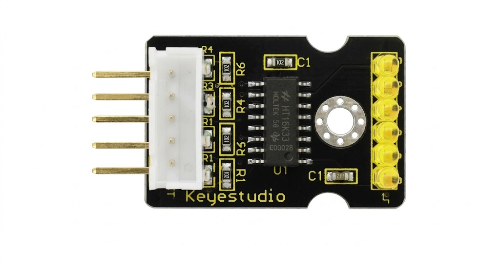
The Keyestudio 5V Stepper Motor Driver Module is a compact and efficient solution for controlling stepper motors with precision. Designed to operate at 5V, this module enables smooth and accurate movement, making it an excellent choice for robotics, automation, and CNC projects. Its compatibility with various microcontrollers, including Arduino, ensures ease of integration into a wide range of applications.
Explore Projects Built with keyestudio 5V stepper motor driver module


Explore Projects Built with keyestudio 5V stepper motor driver module
Common Applications:
- Robotics and automation systems
- CNC machines and 3D printers
- Camera sliders and gimbals
- Precision positioning systems
- Educational and DIY electronics projects
Technical Specifications
Below are the key technical details of the Keyestudio 5V Stepper Motor Driver Module:
| Parameter | Specification |
|---|---|
| Operating Voltage | 5V DC |
| Current Output | Up to 1.5A per phase (motor-dependent) |
| Step Resolution | Full-step, half-step |
| Control Interface | Digital input (IN1, IN2, IN3, IN4) |
| Dimensions | 42mm x 24mm x 12mm |
| Compatible Motors | 4-phase, 5-wire stepper motors |
Pin Configuration and Descriptions
The module features a simple pinout for easy connection to microcontrollers and stepper motors:
| Pin Name | Type | Description |
|---|---|---|
| IN1 | Digital Input | Controls the first coil of the stepper motor |
| IN2 | Digital Input | Controls the second coil of the stepper motor |
| IN3 | Digital Input | Controls the third coil of the stepper motor |
| IN4 | Digital Input | Controls the fourth coil of the stepper motor |
| VCC | Power Input | Connect to 5V power supply |
| GND | Ground | Connect to the ground of the power supply |
| Motor Pins | Output | Connect to the stepper motor (5-wire configuration) |
Usage Instructions
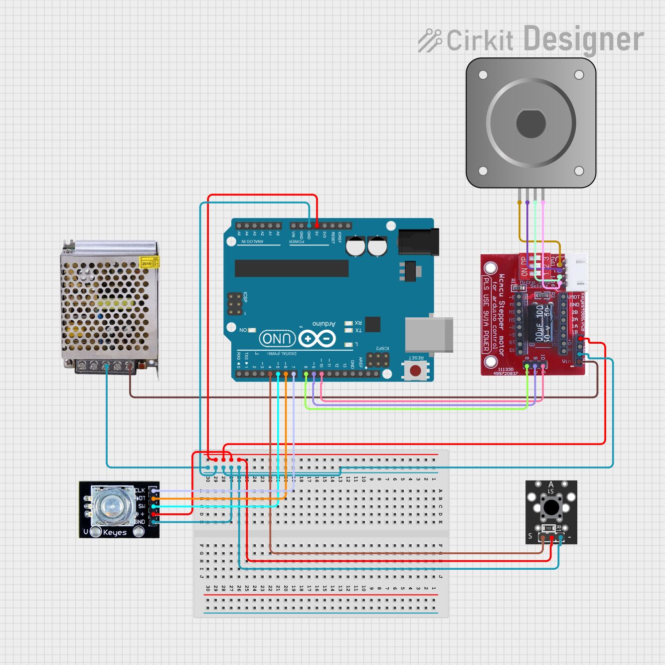
How to Use the Module in a Circuit
- Power Supply: Connect the VCC pin to a 5V power source and the GND pin to the ground.
- Motor Connection: Attach the 5 wires of the stepper motor to the motor output pins on the module.
- Microcontroller Interface: Connect the IN1, IN2, IN3, and IN4 pins to the digital output pins of your microcontroller (e.g., Arduino).
- Programming: Write a program to send step sequences to the IN pins to control the motor's movement.
Important Considerations:
- Ensure the motor's current rating does not exceed the module's maximum output current.
- Use a separate power supply for the motor if it requires higher current than the microcontroller can provide.
- Avoid disconnecting the motor while the module is powered to prevent damage.
Example Code for Arduino UNO
Below is an example code to control a stepper motor using the Keyestudio 5V Stepper Motor Driver Module:
// Define the pins connected to the stepper motor driver module
#define IN1 8  // Connect to IN1 on the module
#define IN2 9  // Connect to IN2 on the module
#define IN3 10 // Connect to IN3 on the module
#define IN4 11 // Connect to IN4 on the module

// Define the step sequence for the stepper motor
int stepSequence[4][4] = {
  {1, 0, 0, 1}, // Step 1
  {1, 0, 1, 0}, // Step 2
  {0, 1, 1, 0}, // Step 3
  {0, 1, 0, 1}  // Step 4
};

void setup() {
  // Set the IN pins as outputs
  pinMode(IN1, OUTPUT);
  pinMode(IN2, OUTPUT);
  pinMode(IN3, OUTPUT);
  pinMode(IN4, OUTPUT);
}

void loop() {
  // Rotate the motor in one direction
  for (int i = 0; i < 4; i++) {
    setStep(stepSequence[i]);
    delay(10); // Adjust delay for speed control
  }
}

// Function to set the step sequence
void setStep(int step[4]) {
  digitalWrite(IN1, step[0]);
  digitalWrite(IN2, step[1]);
  digitalWrite(IN3, step[2]);
  digitalWrite(IN4, step[3]);
}
Notes:
- Adjust the
delay()value in theloop()function to control the motor's speed. - Reverse the order of the step sequence to change the motor's direction.
Troubleshooting and FAQs
Common Issues and Solutions:
Motor Not Moving:
- Verify all connections, especially the motor wires and IN pins.
- Ensure the power supply is providing a stable 5V.
- Check the step sequence in the code for accuracy.
Motor Vibrates but Does Not Rotate:
- Ensure the step sequence matches the motor's wiring configuration.
- Reduce the delay between steps to provide smoother operation.
Overheating Module:
- Check if the motor's current exceeds the module's rating.
- Use a heat sink or active cooling if necessary.
Erratic Movement:
- Verify that the microcontroller's ground is connected to the module's ground.
- Ensure the power supply is not fluctuating.
FAQs:
Q1: Can I use this module with a 3.3V microcontroller?
A1: Yes, but you must ensure the logic level of the IN pins is compatible with 3.3V signals.
Q2: What type of stepper motors are compatible?
A2: The module is designed for 4-phase, 5-wire stepper motors. Ensure the motor's voltage and current ratings match the module's specifications.
Q3: How do I reverse the motor's direction?
A3: Reverse the order of the step sequence in your code to change the motor's rotation direction.
Q4: Can I control multiple motors with one Arduino?
A4: Yes, but you will need a separate driver module for each motor and sufficient digital pins on the Arduino.
By following this documentation, you can effectively use the Keyestudio 5V Stepper Motor Driver Module in your projects.