How to Use circuit breaker: Examples, Pinouts, and Specs
Introduction
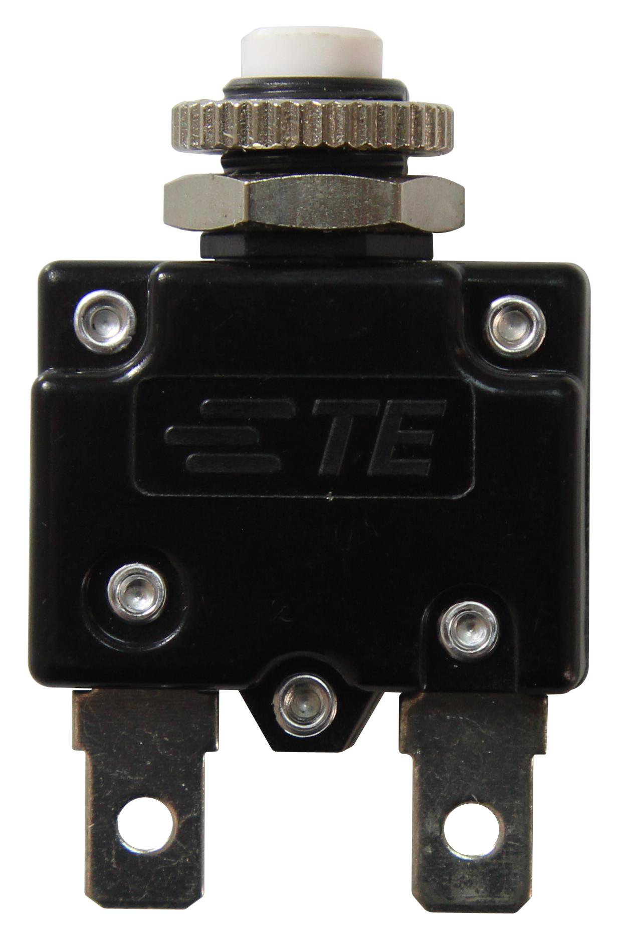
A circuit breaker is an automatic switch designed to protect electrical circuits from damage caused by overloads or short circuits. When a fault is detected, the circuit breaker interrupts the flow of electricity, preventing potential hazards such as fires or equipment damage. Unlike fuses, circuit breakers can be reset manually or automatically after the fault is resolved, making them reusable and highly reliable.
Explore Projects Built with circuit breaker
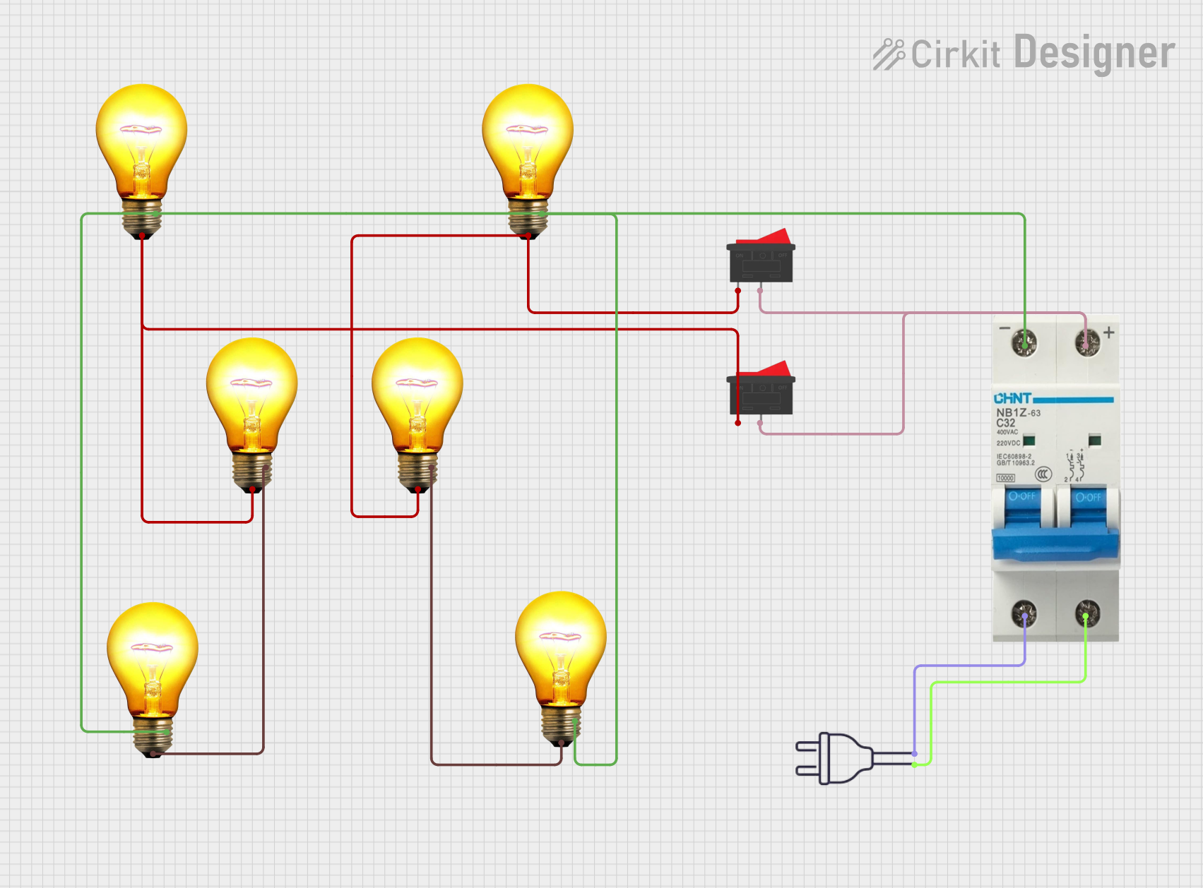
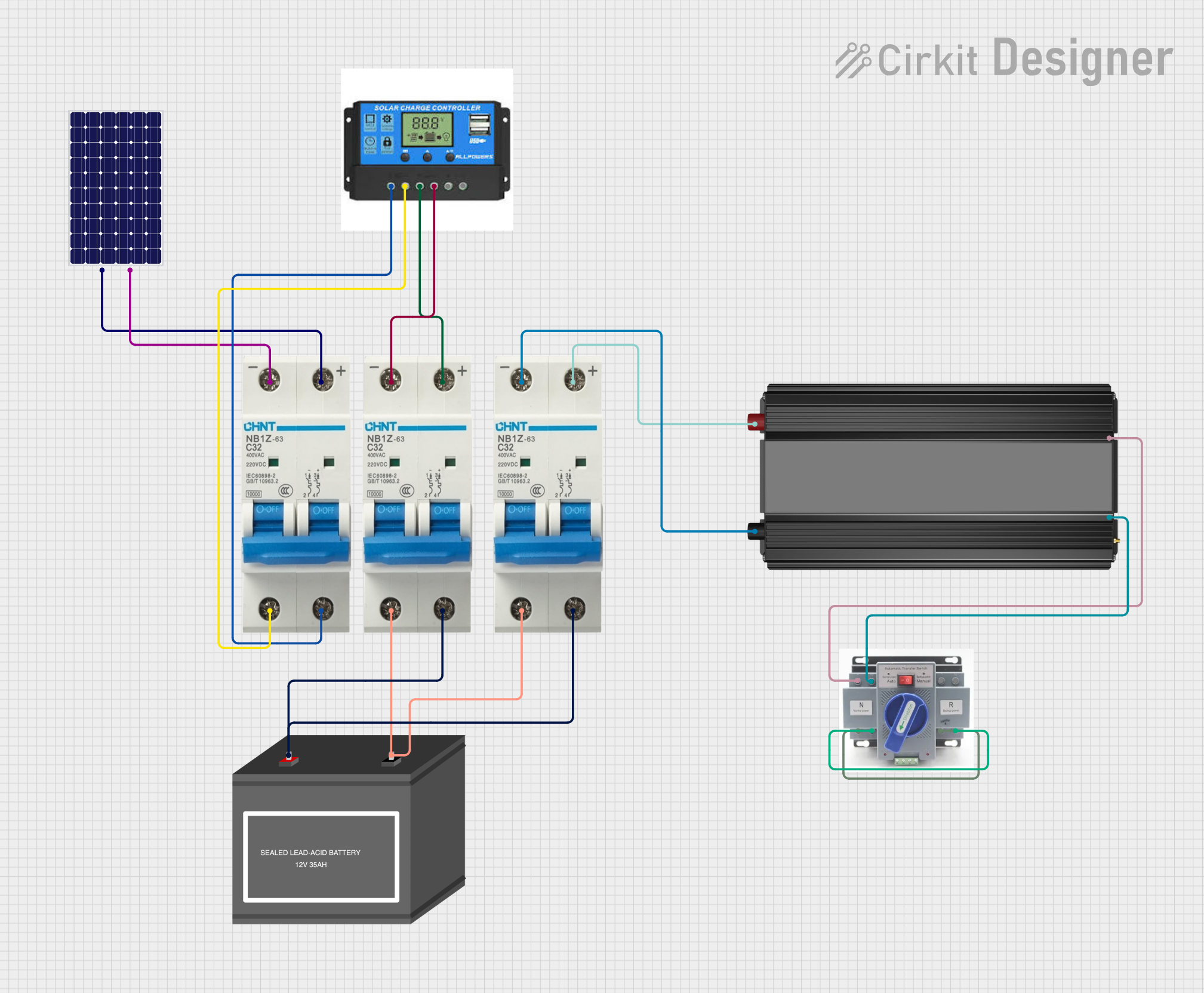


Explore Projects Built with circuit breaker
Common Applications and Use Cases
- Residential and commercial electrical systems for overload and short circuit protection.
- Industrial machinery to safeguard equipment from electrical faults.
- Power distribution systems in substations and grids.
- Automotive electrical systems to protect wiring and components.
- Renewable energy systems, such as solar inverters, to ensure safe operation.
Technical Specifications
Below are the general technical specifications for a typical circuit breaker. Note that specific models may vary depending on the manufacturer and application.
Key Technical Details
- Rated Voltage: 120V AC, 240V AC, or higher (depending on the model).
- Rated Current: Common ratings include 10A, 16A, 20A, 32A, 50A, etc.
- Breaking Capacity: Typically ranges from 6kA to 25kA.
- Trip Mechanism: Thermal, magnetic, or a combination of both.
- Response Time: Instantaneous for short circuits; delayed for overloads.
- Reset Mechanism: Manual or automatic reset options available.
- Mounting Type: DIN rail or panel-mounted.
Pin Configuration and Descriptions
Circuit breakers typically have input and output terminals for connecting to the electrical circuit. Below is a general description of the terminals:
| Pin/Terminal | Description |
|---|---|
| Line (Input) | Connects to the power source or upstream circuit. |
| Load (Output) | Connects to the downstream circuit or load being protected. |
| Ground (Optional) | Some models include a ground terminal for additional safety and fault handling. |
Usage Instructions
How to Use the Component in a Circuit
- Determine the Specifications: Select a circuit breaker with a rated voltage and current suitable for your application.
- Connect the Terminals:
- Connect the Line (Input) terminal to the power source.
- Connect the Load (Output) terminal to the circuit or device being protected.
- If applicable, connect the Ground terminal to the system ground.
- Mount the Circuit Breaker: Secure the breaker on a DIN rail or panel as per the installation requirements.
- Test the Circuit: After installation, test the circuit breaker by simulating an overload or short circuit to ensure proper operation.
Important Considerations and Best Practices
- Always ensure the circuit breaker is rated for the voltage and current of your system.
- Avoid exceeding the breaking capacity of the circuit breaker, as this may result in failure.
- Regularly inspect the circuit breaker for signs of wear or damage.
- For critical applications, consider using a combination of circuit breakers and fuses for added protection.
- When using in conjunction with microcontrollers like Arduino, ensure the circuit breaker is placed on the power supply line to protect the entire system.
Example: Using a Circuit Breaker with an Arduino UNO
While circuit breakers are not directly programmable, they can be used to protect the power supply line of an Arduino-based project. Below is an example of how to integrate a circuit breaker into an Arduino circuit:
// Example Arduino code for monitoring a circuit breaker-protected system
// This code assumes a sensor is used to detect power loss after the breaker trips.

const int sensorPin = A0;  // Analog pin connected to a voltage sensor
const int threshold = 500; // Voltage threshold for detecting power loss

void setup() {
  Serial.begin(9600); // Initialize serial communication
  pinMode(sensorPin, INPUT); // Set the sensor pin as input
}

void loop() {
  int sensorValue = analogRead(sensorPin); // Read the sensor value
  if (sensorValue < threshold) {
    // If voltage drops below the threshold, assume breaker has tripped
    Serial.println("Power loss detected! Check the circuit breaker.");
  } else {
    Serial.println("System operating normally.");
  }
  delay(1000); // Wait for 1 second before the next reading
}
Troubleshooting and FAQs
Common Issues Users Might Face
Circuit Breaker Trips Frequently:
- Cause: Overloaded circuit or short circuit.
- Solution: Reduce the load on the circuit or inspect for wiring faults.
Circuit Breaker Does Not Trip:
- Cause: Faulty breaker or incorrect specifications.
- Solution: Replace the breaker or verify that it matches the system requirements.
Breaker Cannot Be Reset:
- Cause: Persistent fault in the circuit or mechanical failure.
- Solution: Identify and resolve the fault before attempting to reset. Replace the breaker if necessary.
Overheating of Circuit Breaker:
- Cause: Loose connections or prolonged operation near the rated current.
- Solution: Tighten connections and ensure the breaker is not overloaded.
Solutions and Tips for Troubleshooting
- Use a multimeter to check for continuity and voltage levels across the breaker terminals.
- Inspect the wiring and connections for signs of damage or corrosion.
- If the breaker trips during normal operation, consider upgrading to a higher-rated model.
- For complex systems, consult a licensed electrician or engineer to ensure proper installation and operation.