How to Use RAMPS1.4.: Examples, Pinouts, and Specs
Introduction
The RepRap Arduino Mega Pololu Shield (RAMPS) 1.4 is an open-source electronic circuit board designed for controlling 3D printers and other CNC devices. It interfaces with an Arduino Mega 2560 board and controls various components of a 3D printer, such as stepper motors, hotend, heated bed, and fans. RAMPS 1.4 is widely used in the DIY 3D printing community due to its modular design and ease of use.
Explore Projects Built with RAMPS1.4.
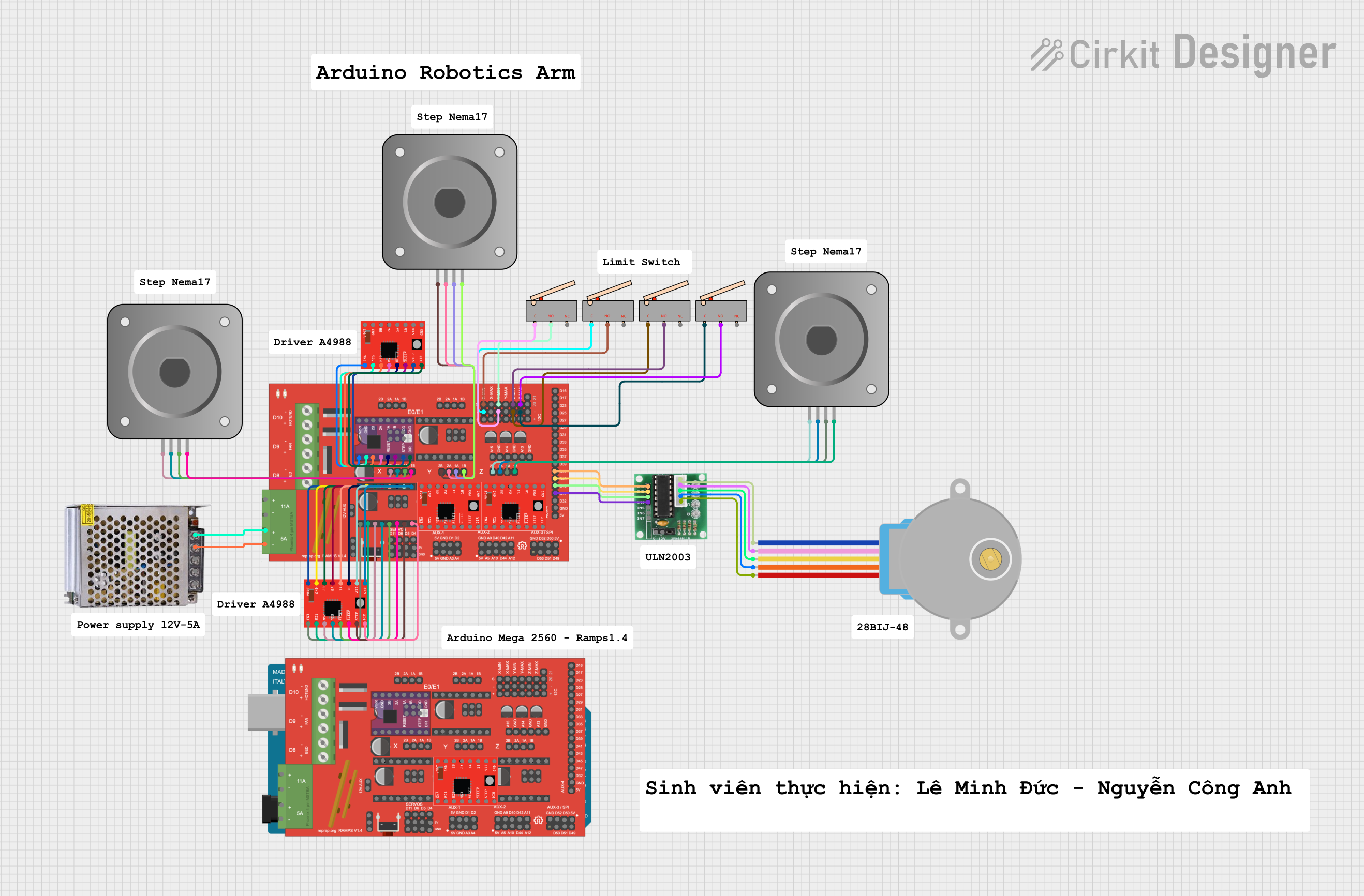

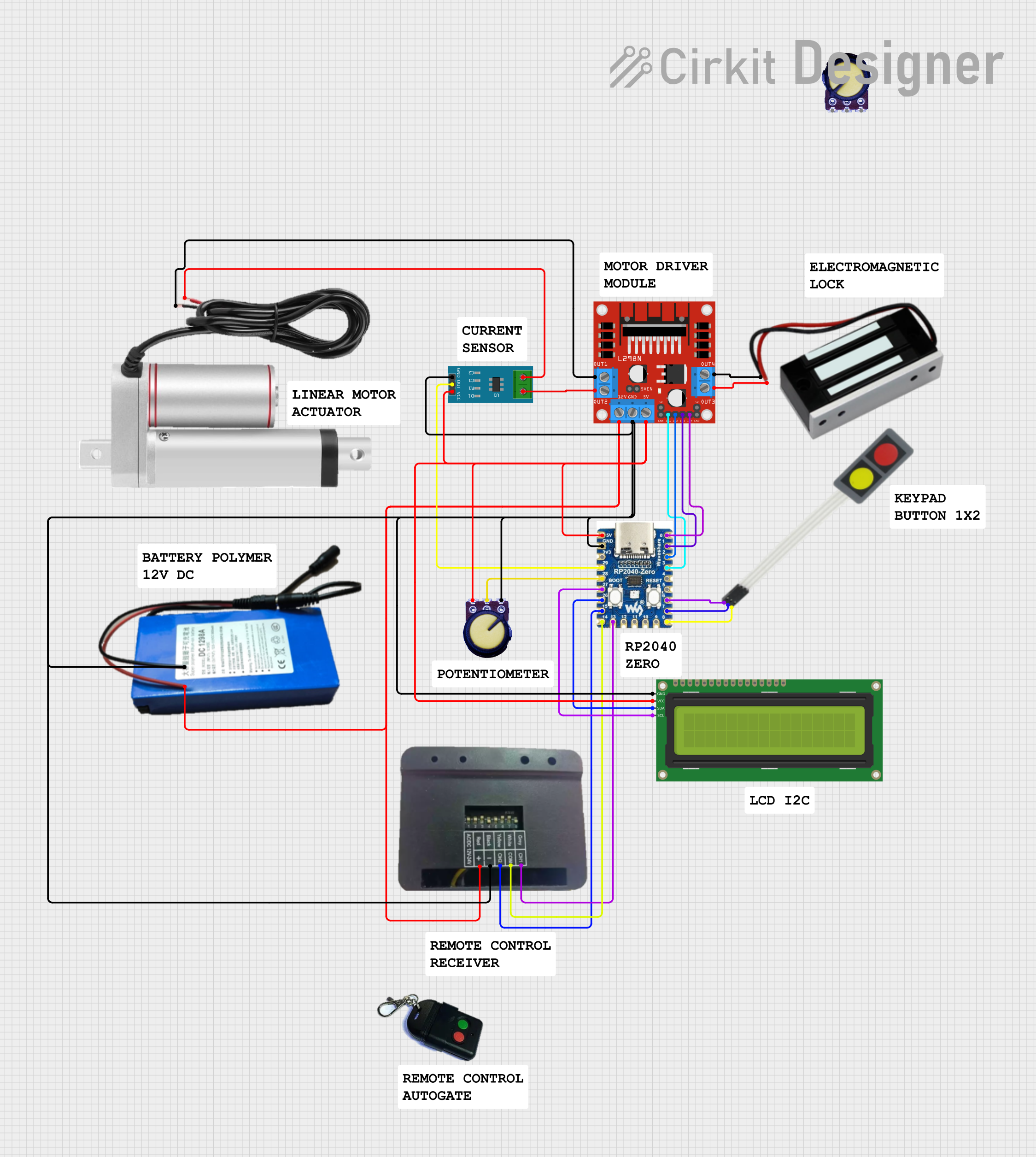
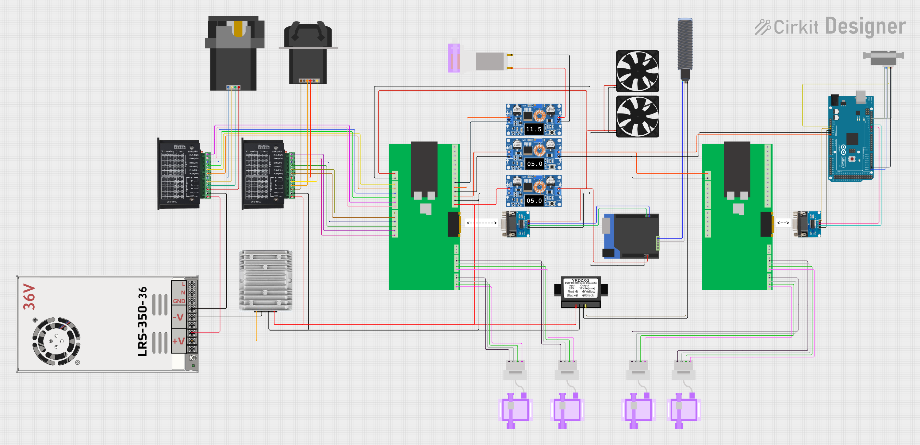
Explore Projects Built with RAMPS1.4.
Common Applications and Use Cases
- 3D Printers
- CNC Machines
- Robotics
- DIY Electronics Projects
Technical Specifications
Key Technical Details
- Operating Voltage: 12V-24V
- Stepper Motor Drivers: 5 slots for A4988 or DRV8825
- Heated Bed Control: 1 channel, up to 11A
- Extruder Control: 2 channels, for dual extrusion
- Thermistor Inputs: 3 channels
- Endstop Inputs: 6 channels
- Expandable with additional modules
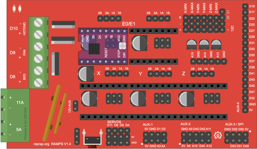
Pin Configuration and Descriptions
| Pin Number | Description | Functionality |
|---|---|---|
| D1 | X-Axis Stepper Driver Enable | Controls the enable pin of X-axis stepper driver |
| D2 | Y-Axis Stepper Driver Enable | Controls the enable pin of Y-axis stepper driver |
| D3 | Z-Axis Stepper Driver Enable | Controls the enable pin of Z-axis stepper driver |
| D4 | Heated Bed | PWM control for the heated bed |
| D5 | Fan | PWM control for cooling fan |
| D6 | Extruder 0 Heater | PWM control for the first extruder heater |
| D7 | Extruder 1 Heater | PWM control for the second extruder heater |
| A0-A2 | Thermistors | Analog inputs for temperature sensors |
| SDA, SCL | I2C Interface | Used for I2C communication |
| 5V, GND | Power Supply | 5V power supply and ground |
Note: This is a simplified pin configuration. For a complete pinout, refer to the RAMPS 1.4 schematic.
Usage Instructions
How to Use the Component in a Circuit
Power Supply: Connect a 12V-24V power supply to the RAMPS 1.4 board. Ensure the power supply is capable of delivering sufficient current for all connected devices.
Stepper Drivers: Insert A4988 or DRV8825 stepper motor drivers into the designated slots, ensuring proper orientation. Adjust the current limit potentiometer on each driver according to the stepper motor specifications.
Connecting Motors and Endstops: Connect stepper motors to the X, Y, Z, and extruder connectors. Attach endstops to the corresponding pins for each axis.
Heating Elements: Connect the hotend and heated bed to their respective terminals, ensuring correct polarity.
Thermistors: Attach thermistors for temperature monitoring to the A0-A2 pins.
Cooling Fans: Connect any cooling fans to the D5 pin for PWM control.
Arduino Mega 2560: Mount the RAMPS 1.4 shield onto an Arduino Mega 2560 board.
Important Considerations and Best Practices
- Always disconnect power before making or changing connections.
- Double-check wiring for correct polarity and secure connections.
- Use proper cooling for the stepper drivers to prevent overheating.
- Ensure firmware (such as Marlin) is correctly configured for your specific setup.
- Calibrate the printer after assembly for accurate prints.
Troubleshooting and FAQs
Common Issues
- Stepper Motors Not Moving: Check connections, ensure drivers are properly seated, and verify firmware settings.
- Heated Bed Not Heating: Ensure the power supply can handle the current draw and that the wiring is correct.
- Thermal Runaway Errors: Check thermistor connections and placement. Ensure firmware safety features are enabled.
Solutions and Tips for Troubleshooting
- If a stepper motor driver overheats, add a heatsink and improve cooling.
- For persistent thermal issues, verify the thermistor's resistance matches the expected value at room temperature.
- Use a multimeter to check for continuity and proper voltage levels at various points on the board.
FAQs
Q: Can I use RAMPS 1.4 with 24V? A: Yes, RAMPS 1.4 can handle 24V, but ensure all connected components are rated for that voltage.
Q: How do I update the firmware for RAMPS 1.4? A: Firmware can be updated via the Arduino IDE. Download the appropriate firmware (e.g., Marlin), configure it for your printer, and upload it to the Arduino Mega 2560.
Q: Can I control additional accessories with RAMPS 1.4? A: Yes, RAMPS 1.4 has expansion headers for adding more functionality, such as additional stepper drivers or sensors.
Example Arduino Code
Below is an example of initializing the stepper motors and endstops in a typical 3D printer firmware setup using RAMPS 1.4:
#include <AccelStepper.h>

// Define stepper motor connections and motor interface type
#define motorInterfaceType 1

// Initialize stepper motors for X, Y, and Z axis
AccelStepper stepperX(motorInterfaceType, 54, 55); // X-axis stepper
AccelStepper stepperY(motorInterfaceType, 60, 61); // Y-axis stepper
AccelStepper stepperZ(motorInterfaceType, 46, 48); // Z-axis stepper

void setup() {
  // Set the maximum speed in steps per second:
  stepperX.setMaxSpeed(1000);
  stepperY.setMaxSpeed(1000);
  stepperZ.setMaxSpeed(500);
}

void loop() {
  // Control stepper motors
  stepperX.moveTo(1000); // Move X-axis stepper to position 1000
  stepperY.moveTo(1000); // Move Y-axis stepper to position 1000
  stepperZ.moveTo(400);  // Move Z-axis stepper to position 400

  // Check if the steppers have reached their set positions
  if (stepperX.distanceToGo() == 0 && stepperY.distanceToGo() == 0 && stepperZ.distanceToGo() == 0) {
    // Perform other actions or update positions
  }

  // Run the stepper motors
  stepperX.run();
  stepperY.run();
  stepperZ.run();
}
Note: This code is for illustrative purposes. Actual implementation will vary based on the specific requirements of your 3D printer and the firmware used.
Remember to consult the RAMPS 1.4 schematic and your 3D printer's documentation for accurate pin assignments and configurations.