How to Use ESP32-WROVER Burning Testing Mini System development Board for ESP-WROOM-32/ ESP-32S/ ESP32-WROVER: Examples, Pinouts, and Specs
Introduction
The ESP32-WROVER Burning Testing Mini System Development Board (Manufacturer: Hailege, Part ID: EC-DTE03033B) is a compact and versatile development board designed for programming, testing, and prototyping with ESP32 modules, including the ESP32-WROVER, ESP-WROOM-32, and ESP-32S. This board provides essential interfaces and features to streamline the development process, making it ideal for IoT applications, embedded systems, and rapid prototyping.
Explore Projects Built with ESP32-WROVER Burning Testing Mini System development Board for ESP-WROOM-32/ ESP-32S/ ESP32-WROVER


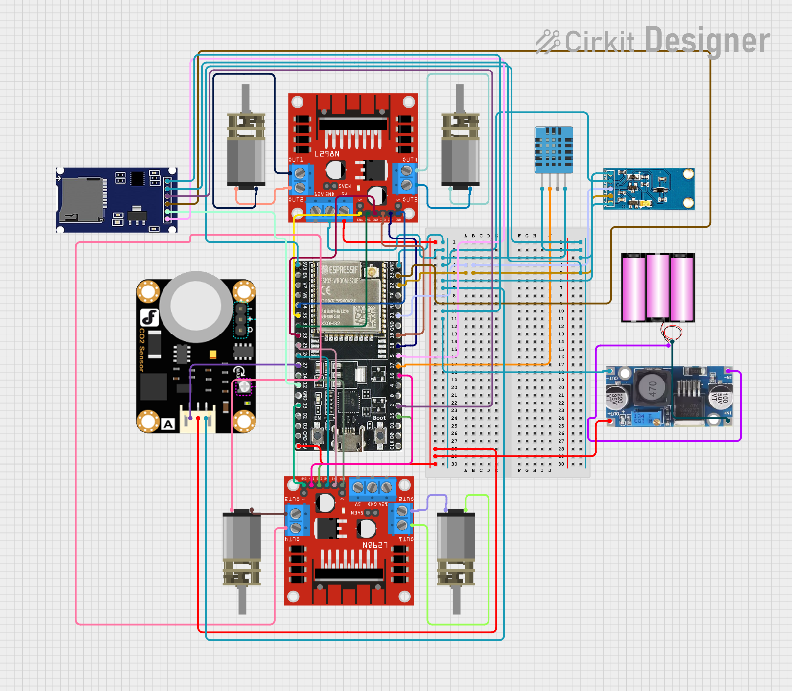
Explore Projects Built with ESP32-WROVER Burning Testing Mini System development Board for ESP-WROOM-32/ ESP-32S/ ESP32-WROVER
Common Applications and Use Cases
- Firmware development and testing for ESP32 modules
- IoT device prototyping and debugging
- Educational projects and learning platforms
- Small-scale production programming
- Wireless communication and sensor integration
Technical Specifications
The following table outlines the key technical specifications of the ESP32-WROVER Burning Testing Mini System Development Board:
| Parameter | Specification |
|---|---|
| Supported Modules | ESP32-WROVER, ESP-WROOM-32, ESP-32S |
| Power Supply Voltage | 5V (via USB) or 3.3V (via external power source) |
| Communication Interface | USB-to-UART (CP2102 or CH340 chip, depending on the version) |
| GPIO Access | Breakout pins for GPIO, UART, SPI, I2C, and other interfaces |
| Flash Button | Integrated button for entering bootloader mode |
| Reset Button | Integrated reset button |
| Dimensions | Compact design, approximately 50mm x 25mm |
| Operating Temperature Range | -40°C to 85°C |
| USB Connector | Micro-USB for power and data communication |
| LED Indicators | Power and status LEDs for easy debugging |
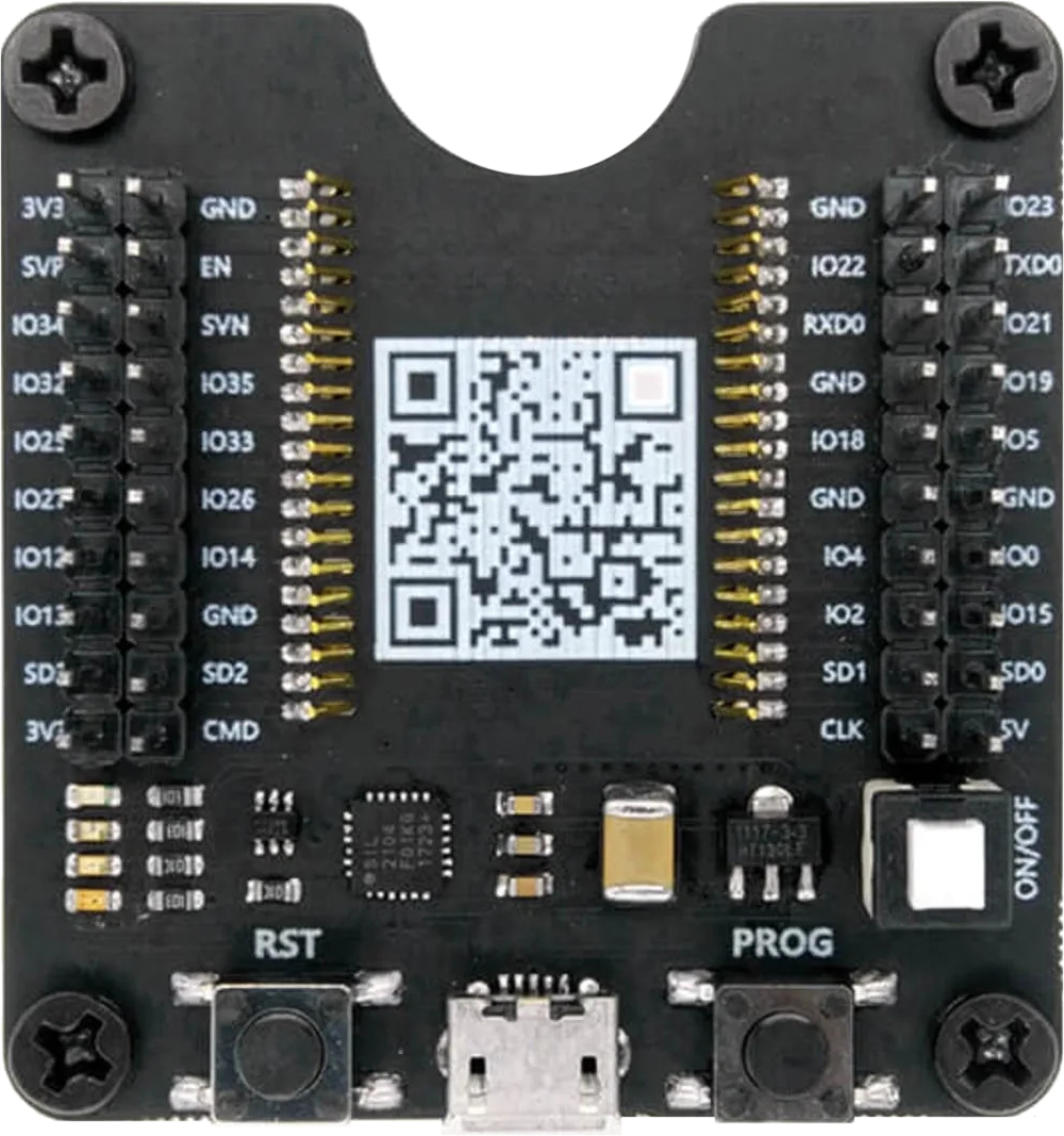
Pin Configuration and Descriptions
The board provides a breakout for the ESP32 module's pins. Below is the pin configuration:
| Pin Name | Description |
|---|---|
| 3V3 | 3.3V power output |
| GND | Ground |
| TXD | UART Transmit (connected to USB-to-UART chip) |
| RXD | UART Receive (connected to USB-to-UART chip) |
| IO0 | GPIO0 (used for entering bootloader mode when pulled low during reset) |
| EN | Enable pin (used to reset the ESP32 module) |
| GPIO Pins | General-purpose input/output pins for interfacing with peripherals |
| SPI Pins | SPI interface pins for connecting to external devices |
| I2C Pins | I2C interface pins for communication with sensors and other peripherals |
Usage Instructions
How to Use the Component in a Circuit
Powering the Board:
- Connect the board to your computer or a USB power source using a Micro-USB cable.
- Alternatively, supply 3.3V to the
3V3pin and connectGNDto ground.
Programming the ESP32 Module:
- Install the necessary USB-to-UART driver (CP2102 or CH340) on your computer.
- Use the Arduino IDE or ESP-IDF to write and upload code to the ESP32 module.
- To enter bootloader mode, press and hold the
Flashbutton, then press and release theResetbutton.
Connecting Peripherals:
- Use the GPIO, SPI, or I2C pins to connect sensors, actuators, or other peripherals.
- Ensure that the connected devices operate within the 3.3V logic level to avoid damage.
Debugging:
- Use the onboard LEDs to monitor power and status.
- Utilize the UART interface for serial communication and debugging.
Important Considerations and Best Practices
- Always verify the pinout of the ESP32 module before connecting peripherals to avoid incorrect wiring.
- Use level shifters if interfacing with 5V logic devices.
- Avoid powering the board via USB and the
3V3pin simultaneously to prevent damage. - Ensure proper ventilation and avoid overheating during prolonged use.
Example Code for Arduino UNO Integration
Below is an example of how to use the ESP32-WROVER Burning Testing Mini System Development Board with an Arduino UNO to send data via UART:
// Example: Sending data from Arduino UNO to ESP32 via UART
// Connect Arduino TX (D1) to ESP32 RXD, and Arduino RX (D0) to ESP32 TXD
// Ensure both devices share a common ground (GND).

void setup() {
  Serial.begin(9600); // Initialize Arduino's serial communication
  delay(1000); // Wait for ESP32 to initialize
  Serial.println("Hello from Arduino!"); // Send data to ESP32
}

void loop() {
  // Continuously send data to ESP32
  Serial.println("Ping from Arduino!");
  delay(1000); // Wait 1 second before sending the next message
}
Troubleshooting and FAQs
Common Issues Users Might Face
ESP32 Not Detected by Computer:
- Ensure the USB cable is functional and supports data transfer.
- Install the correct USB-to-UART driver (CP2102 or CH340).
Unable to Enter Bootloader Mode:
- Verify that the
Flashbutton is pressed and held before pressing theResetbutton. - Check the connection of the
IO0pin to ensure it is pulled low during reset.
- Verify that the
No Output on Serial Monitor:
- Confirm that the baud rate in the serial monitor matches the baud rate in your code.
- Check the wiring of the TXD and RXD pins.
Overheating or Power Issues:
- Avoid powering the board via USB and the
3V3pin simultaneously. - Ensure the connected peripherals do not exceed the board's power capacity.
- Avoid powering the board via USB and the
Solutions and Tips for Troubleshooting
- Use a multimeter to check voltage levels on the
3V3andGNDpins. - Test the board with a simple "blink" program to verify functionality.
- If the board is unresponsive, try re-flashing the firmware using the ESP-IDF or Arduino IDE.
By following this documentation, users can effectively utilize the ESP32-WROVER Burning Testing Mini System Development Board for their development and prototyping needs.