How to Use spdt: Examples, Pinouts, and Specs
Introduction
A Single Pole Double Throw (SPDT) switch is an electrical switch that allows a single input to connect to one of two outputs. This versatile component is commonly used in applications where control over multiple circuits is required from a single switch. SPDT switches are widely utilized in devices such as audio equipment, power supplies, and motor controllers, as well as in logic circuits for signal routing.
Explore Projects Built with spdt

Explore Projects Built with spdt
Common Applications and Use Cases
- Switching between two power sources (e.g., battery and external power)
- Controlling the direction of a DC motor
- Audio signal routing (e.g., selecting between two audio inputs)
- Logic-level signal switching in digital circuits
- Creating simple on/off/on configurations in electrical systems
Technical Specifications
Below are the general technical specifications for a standard SPDT switch. Note that specific values may vary depending on the manufacturer and model.
| Parameter | Specification |
|---|---|
| Switch Type | Single Pole Double Throw (SPDT) |
| Voltage Rating | Typically 3V to 250V (AC or DC) |
| Current Rating | Typically 0.5A to 15A |
| Contact Resistance | ≤ 50 mΩ |
| Insulation Resistance | ≥ 100 MΩ |
| Mechanical Life | 10,000 to 100,000 cycles |
| Operating Temperature | -20°C to 85°C |
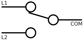
Pin Configuration and Descriptions
An SPDT switch typically has three terminals:
| Pin Name | Description |
|---|---|
| Common (C) | The input terminal that connects to one of the two output terminals. |
| Normally Open (NO) | The terminal that connects to the common terminal when the switch is activated. |
| Normally Closed (NC) | The terminal that connects to the common terminal when the switch is not activated. |
Usage Instructions
How to Use the SPDT Switch in a Circuit
- Identify the Terminals: Locate the Common (C), Normally Open (NO), and Normally Closed (NC) terminals on the switch.
- Connect the Input: Attach the input signal or power source to the Common (C) terminal.
- Connect the Outputs:
- Connect one output circuit to the Normally Open (NO) terminal.
- Connect the other output circuit to the Normally Closed (NC) terminal.
- Control the Switch: Toggle the switch to route the input signal to either the NO or NC terminal, depending on the desired output.
Important Considerations and Best Practices
- Voltage and Current Ratings: Ensure the switch's voltage and current ratings are suitable for your application to avoid damage or failure.
- Debouncing: When using the SPDT switch in digital circuits, consider implementing debouncing techniques (hardware or software) to eliminate signal noise caused by mechanical contacts.
- Wiring: Use appropriate wire gauges and secure connections to prevent loose contacts or overheating.
- Mounting: If the switch is panel-mounted, ensure it is securely fastened to avoid mechanical stress during operation.
Example: Using an SPDT Switch with an Arduino UNO
An SPDT switch can be used to toggle between two LEDs using an Arduino UNO. Below is an example circuit and code:
Circuit Connections
- Connect the Common (C) terminal of the SPDT switch to a digital input pin on the Arduino (e.g., pin 2).
- Connect the Normally Open (NO) terminal to one LED (with a current-limiting resistor) and the Normally Closed (NC) terminal to another LED (with a current-limiting resistor).
- Connect the other ends of the LEDs to ground.
Arduino Code
// Define pin numbers for the SPDT switch and LEDs
const int switchPin = 2;  // SPDT switch common terminal connected to pin 2
const int led1Pin = 3;    // LED 1 connected to Normally Open (NO) terminal
const int led2Pin = 4;    // LED 2 connected to Normally Closed (NC) terminal

void setup() {
  pinMode(switchPin, INPUT_PULLUP); // Configure switch pin as input with pull-up resistor
  pinMode(led1Pin, OUTPUT);         // Configure LED 1 pin as output
  pinMode(led2Pin, OUTPUT);         // Configure LED 2 pin as output
}

void loop() {
  int switchState = digitalRead(switchPin); // Read the state of the SPDT switch

  if (switchState == LOW) {
    // If the switch is toggled to the NO position, turn on LED 1
    digitalWrite(led1Pin, HIGH);
    digitalWrite(led2Pin, LOW);
  } else {
    // If the switch is toggled to the NC position, turn on LED 2
    digitalWrite(led1Pin, LOW);
    digitalWrite(led2Pin, HIGH);
  }
}
Notes:
- The
INPUT_PULLUPmode is used to simplify the circuit by enabling the internal pull-up resistor of the Arduino. - Ensure the current-limiting resistors for the LEDs are appropriately calculated to prevent damage.
Troubleshooting and FAQs
Common Issues and Solutions
Switch Not Functioning Properly
- Cause: Loose or incorrect wiring.
- Solution: Double-check all connections and ensure the terminals are correctly identified.
LEDs Not Lighting Up in Arduino Circuit
- Cause: Incorrect pin configuration or missing pull-up resistor.
- Solution: Verify the pin numbers in the code and ensure the
INPUT_PULLUPmode is enabled.
Switch Generates Noise in Digital Circuits
- Cause: Mechanical contact bounce.
- Solution: Implement a debouncing circuit (e.g., RC filter) or software debouncing in the code.
Overheating or Damage
- Cause: Exceeding the voltage or current ratings of the switch.
- Solution: Use a switch with appropriate ratings for your application.
FAQs
Q: Can I use an SPDT switch to control AC devices?
A: Yes, as long as the switch's voltage and current ratings are suitable for the AC load.
Q: How do I identify the terminals on an SPDT switch?
A: Most SPDT switches have markings or diagrams on the body. If not, use a multimeter to test continuity between the terminals.
Q: Can I use an SPDT switch for PWM signals?
A: Yes, but ensure the switch can handle the frequency and voltage of the PWM signal without introducing significant noise or distortion.