How to Use esp32: Examples, Pinouts, and Specs
Introduction
The ESP32 is a low-cost, low-power system on a chip (SoC) developed by Espressif Systems. It features integrated Wi-Fi and Bluetooth capabilities, making it an ideal choice for Internet of Things (IoT) applications, smart devices, and embedded systems. The ESP32 is highly versatile, offering dual-core processing, a wide range of GPIO pins, and support for various communication protocols.
Explore Projects Built with esp32


Explore Projects Built with esp32
Common Applications and Use Cases
- IoT devices (e.g., smart home systems, sensors, and actuators)
- Wearable technology
- Wireless communication hubs
- Robotics and automation
- Data logging and remote monitoring
- Prototyping and development of connected devices
Technical Specifications
The ESP32 is packed with features that make it a powerful and flexible component for a wide range of applications. Below are its key technical specifications:
Key Technical Details
- Processor: Dual-core Xtensa® 32-bit LX6 microprocessor, up to 240 MHz
- Memory: 520 KB SRAM, 4 MB Flash (varies by model)
- Wi-Fi: 802.11 b/g/n, 2.4 GHz
- Bluetooth: Bluetooth 4.2 and BLE (Bluetooth Low Energy)
- Operating Voltage: 3.0V to 3.6V
- GPIO Pins: 34 programmable GPIOs
- ADC: 12-bit, up to 18 channels
- DAC: 2 channels, 8-bit resolution
- Communication Protocols: SPI, I2C, UART, I2S, CAN, PWM
- Power Consumption: Ultra-low power consumption in deep sleep mode (~10 µA)
- Operating Temperature: -40°C to +125°C
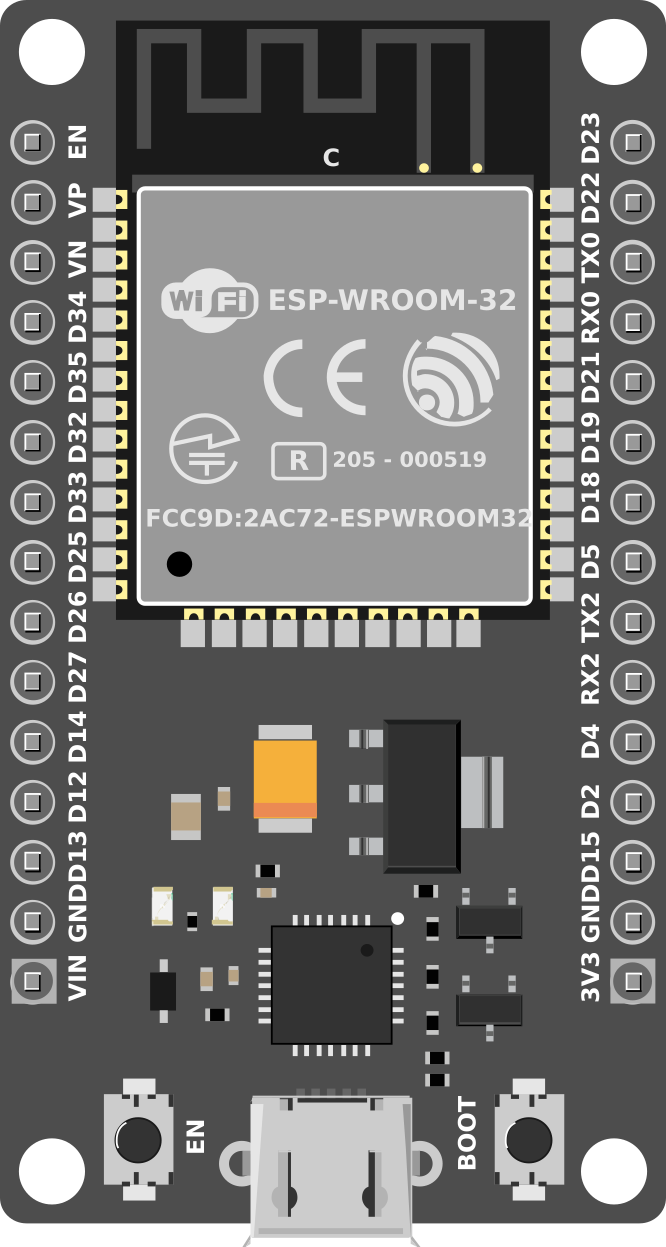
Pin Configuration and Descriptions
The ESP32 has a variety of pins for different functionalities. Below is a table summarizing the key pins and their descriptions:
| Pin Name | Type | Description |
|---|---|---|
| GPIO0 | Digital I/O | General-purpose I/O, also used for boot mode selection. |
| GPIO2 | Digital I/O | General-purpose I/O, often used as a bootstrapping pin. |
| GPIO12 | Digital I/O | General-purpose I/O, can be used for SPI or other functions. |
| GPIO13 | Digital I/O | General-purpose I/O, supports PWM and other functions. |
| GPIO15 | Digital I/O | General-purpose I/O, supports PWM and other functions. |
| EN | Power Control | Chip enable pin. Pulling low disables the chip. |
| 3V3 | Power | 3.3V power supply input/output. |
| GND | Ground | Ground connection. |
| ADC1_0 to ADC1_7 | Analog Input | 12-bit ADC channels for analog signal input. |
| DAC1, DAC2 | Analog Output | 8-bit DAC channels for analog signal output. |
| TX0, RX0 | UART | Default UART0 pins for serial communication. |
| SCL, SDA | I2C | Default I2C clock and data pins. |
| SPI_CLK, SPI_MOSI, SPI_MISO, SPI_CS | SPI | Default SPI clock, data in/out, and chip select pins. |
Note: The exact pinout may vary depending on the ESP32 module or development board you are using (e.g., ESP32-WROOM-32, ESP32-WROVER).
Usage Instructions
How to Use the ESP32 in a Circuit
- Powering the ESP32:
- Connect the 3.3V pin to a regulated 3.3V power source.
- Ensure the GND pin is connected to the ground of your circuit.
- Programming the ESP32:
- Use a USB-to-serial adapter or a development board with a built-in USB interface.
- Install the ESP32 board package in the Arduino IDE or use the Espressif IDF (IoT Development Framework).
- Connecting Peripherals:
- Use GPIO pins for digital input/output.
- Connect sensors to ADC pins for analog input.
- Use I2C, SPI, or UART for communication with other devices.
- Flashing Code:
- Press and hold the "BOOT" button (if available) while uploading code to the ESP32.
Important Considerations and Best Practices
- Voltage Levels: The ESP32 operates at 3.3V logic levels. Avoid connecting 5V signals directly to its GPIO pins.
- Power Supply: Use a stable power source to avoid unexpected resets or malfunctions.
- Deep Sleep Mode: Utilize the deep sleep mode for battery-powered applications to conserve energy.
- Pull-up/Pull-down Resistors: Some GPIO pins require external pull-up or pull-down resistors for proper operation.
- Antenna Placement: Ensure the onboard antenna has sufficient clearance from metal objects to avoid interference.
Example Code for Arduino UNO Integration
Below is an example of how to use the ESP32 with the Arduino IDE to blink an LED connected to GPIO2:
// Example: Blink an LED on GPIO2 of the ESP32

// Define the GPIO pin for the LED
#define LED_PIN 2

void setup() {
  // Initialize the LED pin as an output
  pinMode(LED_PIN, OUTPUT);
}

void loop() {
  // Turn the LED on
  digitalWrite(LED_PIN, HIGH);
  delay(1000); // Wait for 1 second

  // Turn the LED off
  digitalWrite(LED_PIN, LOW);
  delay(1000); // Wait for 1 second
}
Tip: Ensure the ESP32 board is selected in the Arduino IDE under
Tools > Board.
Troubleshooting and FAQs
Common Issues and Solutions
- ESP32 Not Detected by Computer:
- Ensure the correct USB driver is installed (e.g., CP210x or CH340 driver).
- Check the USB cable for data transfer capability (some cables are power-only).
- Code Upload Fails:
- Press and hold the "BOOT" button during the upload process.
- Verify the correct COM port and board are selected in the Arduino IDE.
- Wi-Fi Connection Issues:
- Double-check the SSID and password in your code.
- Ensure the router is operating on the 2.4 GHz band (ESP32 does not support 5 GHz).
- Random Resets or Instability:
- Use a stable power supply with sufficient current (at least 500 mA).
- Avoid using GPIO pins that are reserved for bootstrapping during startup.
FAQs
Q: Can the ESP32 operate on 5V?
A: No, the ESP32 operates at 3.3V. However, many development boards include a voltage regulator to accept 5V input.Q: How do I reset the ESP32?
A: Press the "EN" (Enable) button on the development board to reset the ESP32.Q: Can I use the ESP32 with Bluetooth and Wi-Fi simultaneously?
A: Yes, the ESP32 supports simultaneous use of Bluetooth and Wi-Fi, but performance may vary depending on the application.Q: What is the maximum range of the ESP32's Wi-Fi?
A: The range depends on environmental factors but is typically up to 100 meters in open space.
By following this documentation, you can effectively integrate the ESP32 into your projects and troubleshoot common issues with ease.