
How to Use Mosfet module: Examples, Pinouts, and Specs
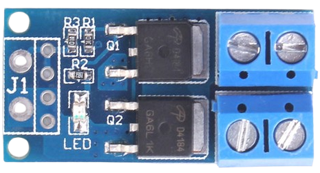
 Design with Mosfet module in Cirkit Designer
Introduction
A MOSFET (Metal-Oxide-Semiconductor Field-Effect Transistor) module is a versatile electronic component designed for switching and amplifying electronic signals. It is widely recognized for its high efficiency, fast switching capabilities, and low power loss. These characteristics make it an essential component in various applications, including power management, motor control, signal processing, and high-speed switching circuits.
Explore Projects Built with Mosfet module
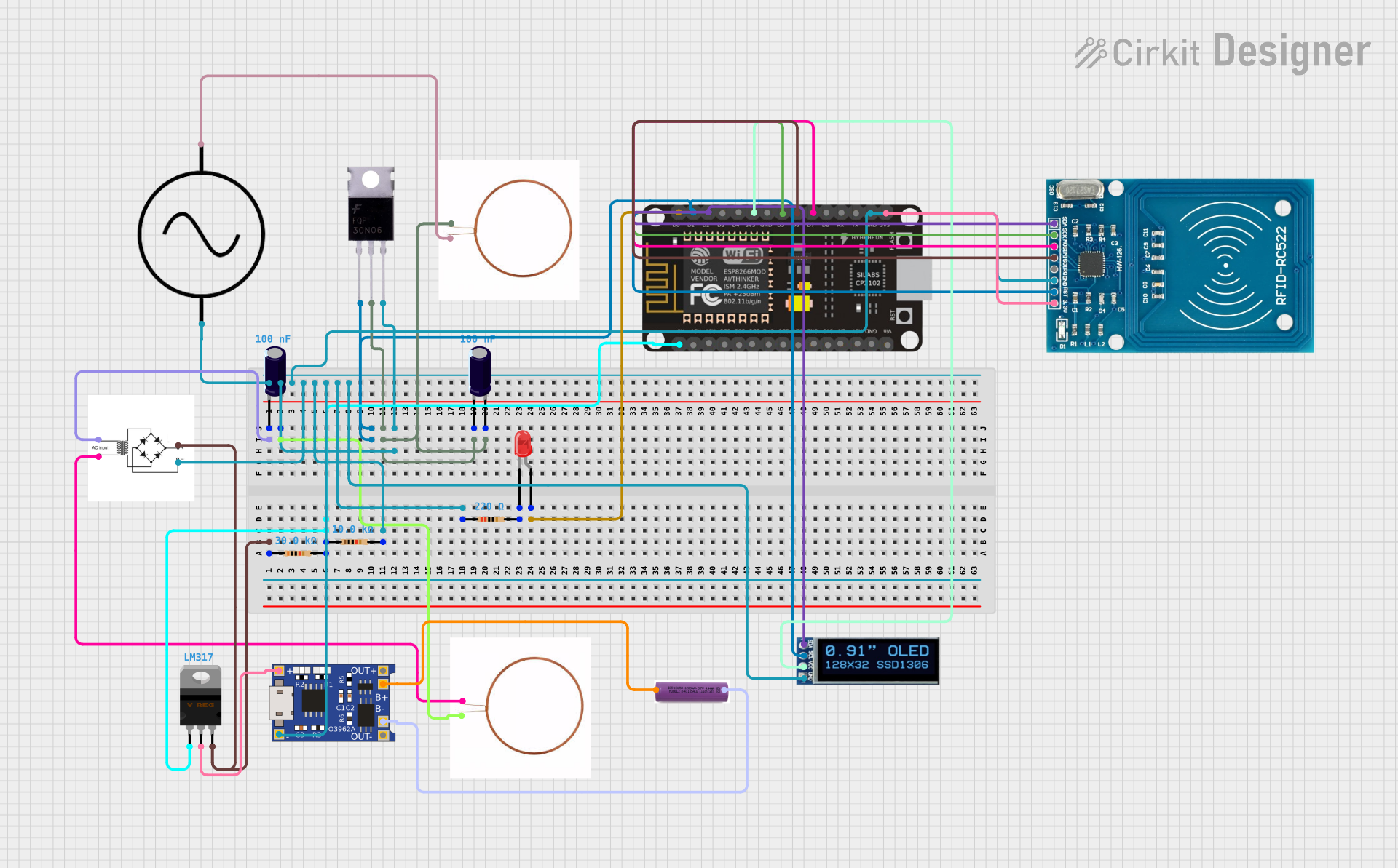 Open Project in Cirkit Designer
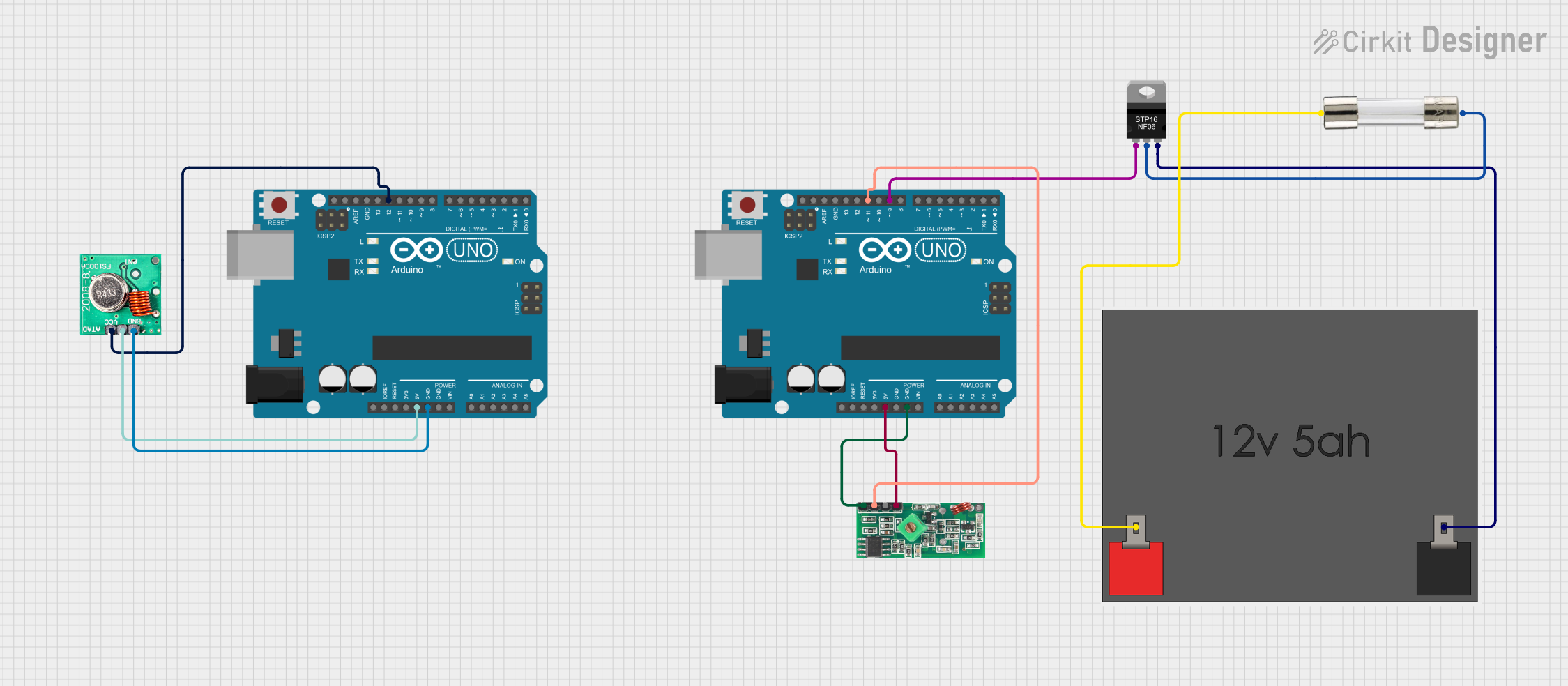 Open Project in Cirkit Designer
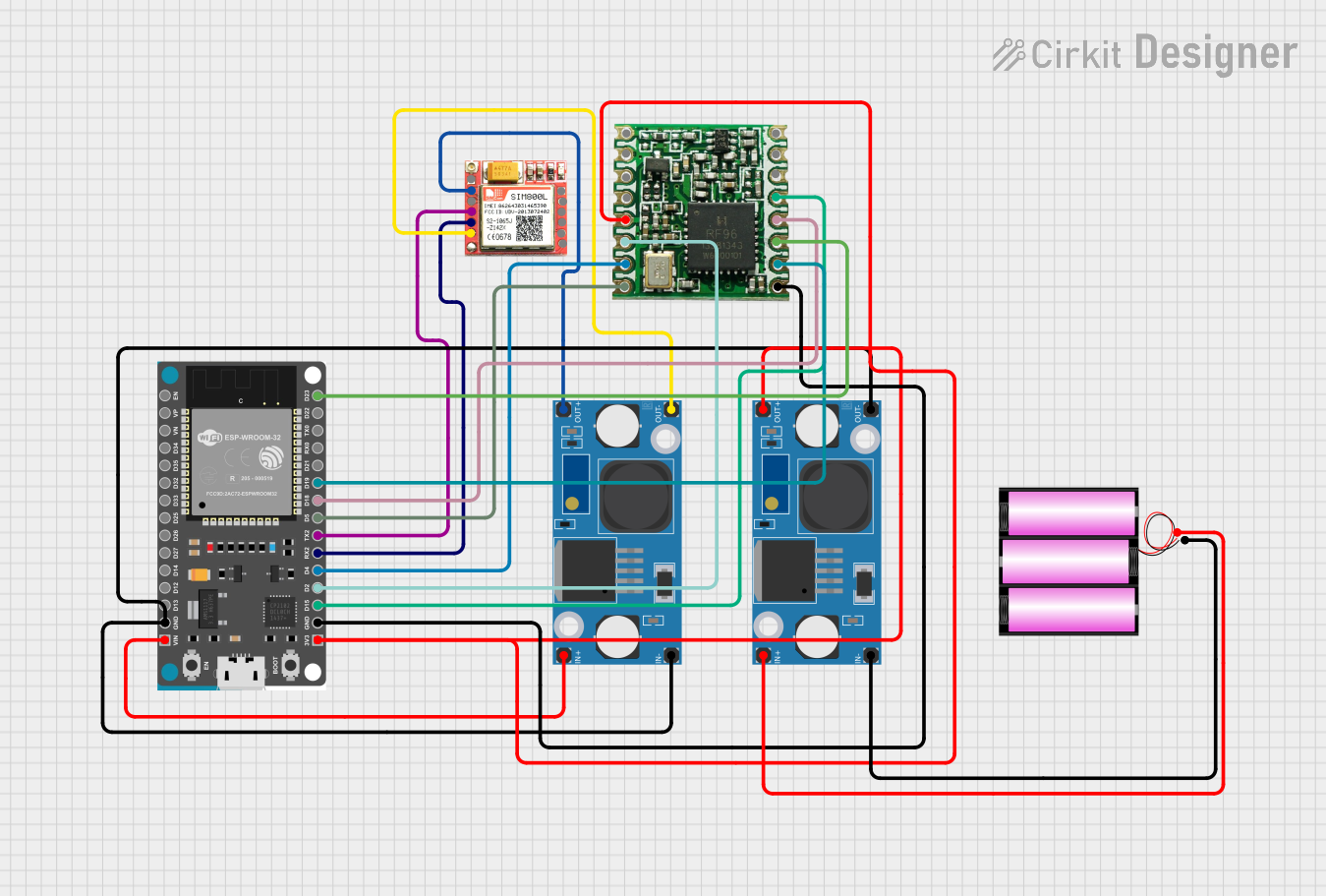 Open Project in Cirkit Designer
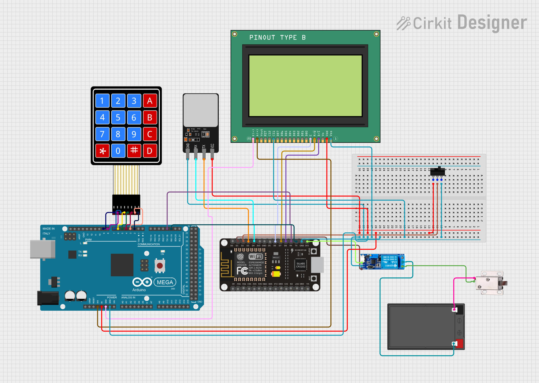 Open Project in Cirkit Designer
Explore Projects Built with Mosfet module
Open Project in Cirkit DesignerOpen Project in Cirkit DesignerOpen Project in Cirkit DesignerOpen Project in Cirkit DesignerCommon Applications
- Power Management: Used in DC-DC converters, voltage regulators, and power supplies.
- Motor Control: Drives motors in robotics, industrial automation, and electric vehicles.
- Signal Processing: Amplifies weak signals in audio and RF circuits.
- Switching Circuits: Operates as a high-speed switch in digital and analog circuits.
Technical Specifications
Below are the general technical specifications for a typical MOSFET module. Always refer to the specific datasheet for the exact part number for precise details.
Key Specifications
- Voltage Rating (VDS): Up to 100V (varies by model)
- Current Rating (ID): Up to 30A (varies by model)
- Gate Threshold Voltage (VGS(th)): 2V to 4V
- RDS(on): As low as 0.01Ω
- Switching Speed: Nanoseconds range
- Operating Temperature: -55°C to +150°C
Pin Configuration
The MOSFET module typically has three main pins: Gate (G), Drain (D), and Source (S). Some modules may include additional pins for auxiliary functions. Below is a standard pinout description:
| Pin | Name | Description |
|---|---|---|
| 1 | Gate (G) | Controls the MOSFET's switching state. A voltage applied here turns the MOSFET on or off. |
| 2 | Drain (D) | The main current-carrying terminal. Connects to the load in the circuit. |
| 3 | Source (S) | The return path for current. Typically connected to ground or the negative terminal. |
Usage Instructions
How to Use the MOSFET Module in a Circuit
- Determine the Operating Voltage and Current: Ensure the MOSFET module's voltage and current ratings exceed the requirements of your circuit.
- Connect the Pins:
- Connect the Gate to a control signal (e.g., microcontroller output) through a resistor (typically 220Ω to 1kΩ) to limit inrush current.
- Connect the Drain to the positive side of the load.
- Connect the Source to ground or the negative terminal of the power supply.
- Gate Drive Voltage: Ensure the control signal provides sufficient voltage to fully turn on the MOSFET (check VGS(th) in the datasheet).
- Add a Flyback Diode: For inductive loads (e.g., motors), place a flyback diode across the load to protect the MOSFET from voltage spikes.
Example: Using a MOSFET Module with Arduino UNO
Below is an example of controlling an LED using a MOSFET module and an Arduino UNO:
// Define the MOSFET Gate pin connected to Arduino
const int mosfetGatePin = 9; // Pin 9 is used to control the MOSFET

void setup() {
  pinMode(mosfetGatePin, OUTPUT); // Set the MOSFET Gate pin as an output
}

void loop() {
  digitalWrite(mosfetGatePin, HIGH); // Turn on the MOSFET (LED ON)
  delay(1000); // Wait for 1 second
  digitalWrite(mosfetGatePin, LOW);  // Turn off the MOSFET (LED OFF)
  delay(1000); // Wait for 1 second
}
Best Practices
- Use a gate resistor to limit the inrush current to the Gate pin.
- Ensure the MOSFET operates within its safe operating area (SOA).
- Use a heat sink or cooling mechanism for high-power applications to prevent overheating.
- Avoid exceeding the maximum VGS rating to prevent damage to the Gate.
Troubleshooting and FAQs
Common Issues and Solutions
MOSFET Not Switching Properly:
- Cause: Insufficient Gate drive voltage.
- Solution: Verify the control signal voltage and ensure it meets the VGS(th) requirement.
MOSFET Overheating:
- Cause: Excessive current or inadequate cooling.
- Solution: Check the current through the MOSFET and add a heat sink if necessary.
Load Not Turning On:
- Cause: Incorrect wiring or damaged MOSFET.
- Solution: Double-check the connections and test the MOSFET with a multimeter.
Voltage Spikes Damaging the MOSFET:
- Cause: Inductive load without a flyback diode.
- Solution: Add a flyback diode across the load to suppress voltage spikes.
FAQs
Q: Can I use a MOSFET module with a 3.3V microcontroller?
A: Yes, but ensure the MOSFET's Gate threshold voltage (VGS(th)) is low enough to fully turn on with 3.3V.Q: How do I test if a MOSFET is working?
A: Use a multimeter in diode mode to check the Gate-Source and Drain-Source junctions for proper behavior.Q: What is the purpose of the Gate resistor?
A: It limits the inrush current to the Gate, protecting the microcontroller and reducing noise.
By following this documentation, you can effectively integrate and troubleshoot a MOSFET module in your electronic projects. Always consult the specific datasheet for your MOSFET module for precise details.