How to Use bmx160: Examples, Pinouts, and Specs

Introduction
The BMX160 is a highly integrated 9-axis motion sensor that combines a 3-axis accelerometer, a 3-axis gyroscope, and a 3-axis magnetometer in a single compact package. This sensor is designed for precise motion tracking and orientation detection, making it ideal for applications such as smartphones, wearables, augmented reality (AR) devices, virtual reality (VR) systems, and Internet of Things (IoT) devices. Its low power consumption and high performance make it suitable for battery-powered applications.
Explore Projects Built with bmx160

Explore Projects Built with bmx160
Technical Specifications
The BMX160 offers a range of features and specifications that make it versatile for various motion-sensing applications.
Key Specifications
- Supply Voltage: 1.8V to 3.6V
- Power Consumption:
- Accelerometer: 180 µA (typical)
- Gyroscope: 900 µA (typical)
- Magnetometer: 800 µA (typical)
- Communication Interfaces: I2C, SPI
- Accelerometer Range: ±2g, ±4g, ±8g, ±16g
- Gyroscope Range: ±125°/s, ±250°/s, ±500°/s, ±1000°/s, ±2000°/s
- Magnetometer Range: ±1300 µT (typical)
- Operating Temperature: -40°C to +85°C
- Package: 14-pin LGA, 2.5mm x 3.0mm x 0.95mm
Pin Configuration and Descriptions
The BMX160 has 14 pins, each serving a specific function. Below is the pinout description:
| Pin Number | Pin Name | Description |
|---|---|---|
| 1 | GND | Ground |
| 2 | VDDIO | I/O Voltage Supply |
| 3 | VDD | Core Voltage Supply |
| 4 | CS | Chip Select (SPI) / I2C Address Select |
| 5 | SDO | SPI Data Output / I2C Address Select |
| 6 | SDA/SDI | I2C Data / SPI Data Input |
| 7 | SCL/SCK | I2C Clock / SPI Clock |
| 8 | INT1 | Interrupt 1 Output |
| 9 | INT2 | Interrupt 2 Output |
| 10 | NC | Not Connected |
| 11 | NC | Not Connected |
| 12 | NC | Not Connected |
| 13 | NC | Not Connected |
| 14 | GND | Ground |
Usage Instructions
The BMX160 can be used in a variety of applications, and its integration into a circuit is straightforward. Below are the steps and considerations for using the BMX160.
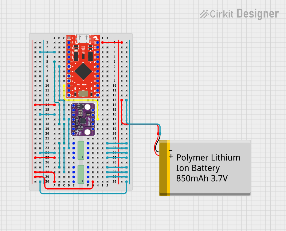
Connecting the BMX160 to an Arduino UNO
The BMX160 can communicate with an Arduino UNO using the I2C protocol. Follow these steps to connect the sensor:
Wiring:
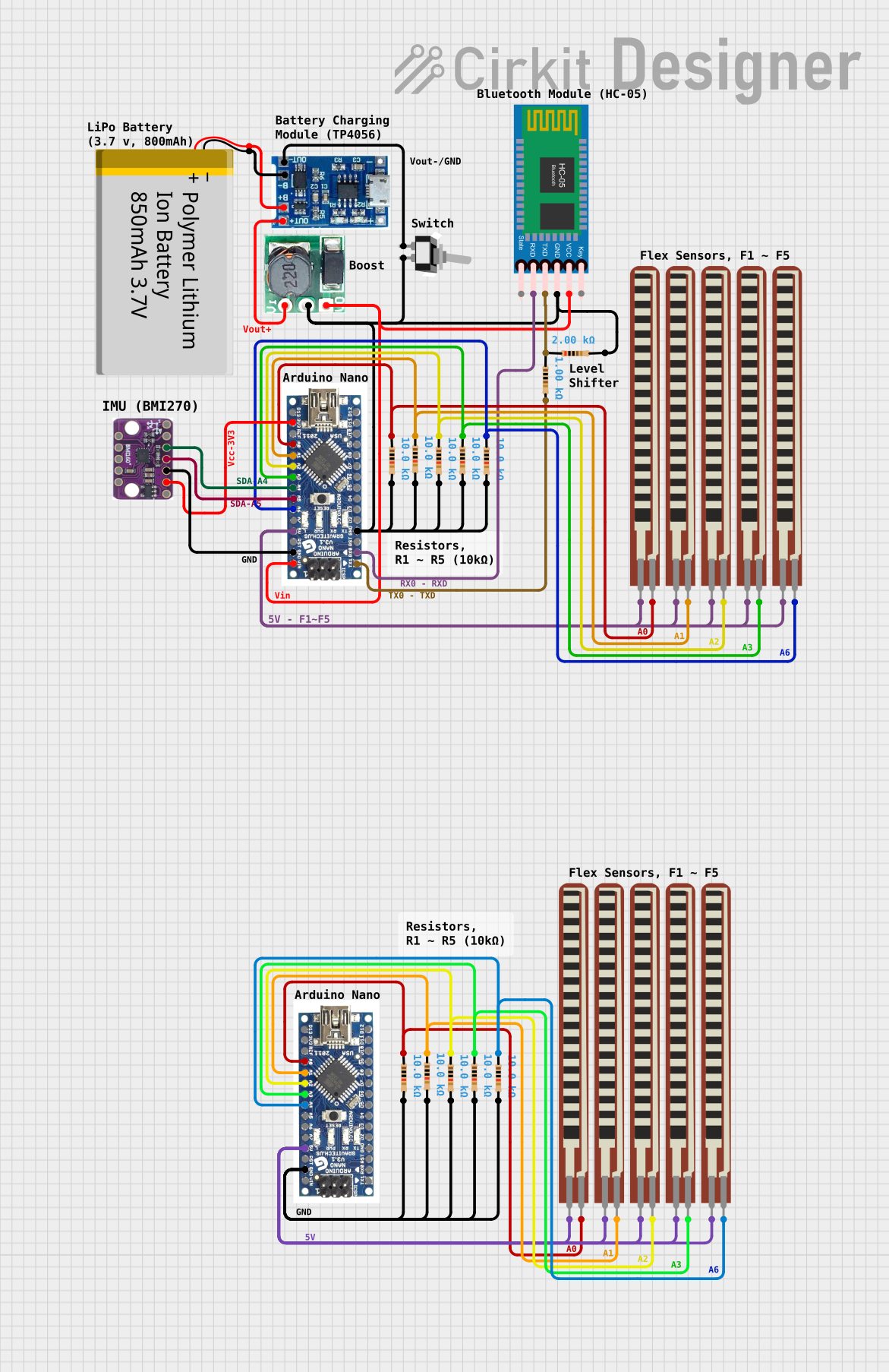
- Connect the VDD pin of the BMX160 to the 3.3V pin on the Arduino.
- Connect the GND pin of the BMX160 to the GND pin on the Arduino.
- Connect the SDA pin of the BMX160 to the A4 pin on the Arduino (I2C data line).
- Connect the SCL pin of the BMX160 to the A5 pin on the Arduino (I2C clock line).
Install the Required Library:
- Use the Arduino IDE Library Manager to install the "Adafruit_BMX160" library or any compatible library for the BMX160.
Example Code: Below is an example Arduino sketch to read accelerometer, gyroscope, and magnetometer data from the BMX160:
#include <Wire.h>
#include <Adafruit_Sensor.h>
#include <Adafruit_BMX160.h>

// Create an instance of the BMX160 sensor
Adafruit_BMX160 bmx160 = Adafruit_BMX160();

void setup() {
  Serial.begin(9600);
  while (!Serial) {
    delay(10); // Wait for Serial Monitor to open
  }

  // Initialize the BMX160 sensor
  if (!bmx160.begin()) {
    Serial.println("Failed to initialize BMX160! Check connections.");
    while (1);
  }
  Serial.println("BMX160 initialized successfully!");
}

void loop() {
  // Variables to store sensor data
  sensors_event_t accel, gyro, mag;

  // Get sensor data
  bmx160.getEvent(&accel, &gyro, &mag);

  // Print accelerometer data
  Serial.print("Accel X: "); Serial.print(accel.acceleration.x); Serial.print(" m/s^2, ");
  Serial.print("Y: "); Serial.print(accel.acceleration.y); Serial.print(" m/s^2, ");
  Serial.print("Z: "); Serial.println(accel.acceleration.z); Serial.println(" m/s^2");

  // Print gyroscope data
  Serial.print("Gyro X: "); Serial.print(gyro.gyro.x); Serial.print(" rad/s, ");
  Serial.print("Y: "); Serial.print(gyro.gyro.y); Serial.print(" rad/s, ");
  Serial.print("Z: "); Serial.println(gyro.gyro.z); Serial.println(" rad/s");

  // Print magnetometer data
  Serial.print("Mag X: "); Serial.print(mag.magnetic.x); Serial.print(" µT, ");
  Serial.print("Y: "); Serial.print(mag.magnetic.y); Serial.print(" µT, ");
  Serial.print("Z: "); Serial.println(mag.magnetic.z); Serial.println(" µT");

  delay(500); // Delay for readability
}
Important Considerations
- Power Supply: Ensure the BMX160 is powered with a voltage within its operating range (1.8V to 3.6V). Using a voltage regulator may be necessary if your system operates at a higher voltage.
- Pull-Up Resistors: For I2C communication, ensure pull-up resistors (typically 4.7kΩ) are connected to the SDA and SCL lines.
- Interrupt Pins: The INT1 and INT2 pins can be used for event-driven applications, such as motion detection or orientation changes.
Troubleshooting and FAQs
Common Issues
Sensor Not Detected:
- Cause: Incorrect wiring or I2C address mismatch.
- Solution: Double-check the connections and ensure the I2C address matches the library settings.
Incorrect or No Data Output:
- Cause: Faulty sensor initialization or incorrect library usage.
- Solution: Verify that the sensor is initialized correctly in the code and that the library is compatible with the BMX160.
High Noise in Sensor Readings:
- Cause: Environmental interference or improper grounding.
- Solution: Ensure proper grounding and minimize external noise sources.
FAQs
Can the BMX160 operate with SPI instead of I2C?
- Yes, the BMX160 supports both I2C and SPI communication protocols. Configure the CS pin and use the appropriate library settings for SPI.
What is the maximum sampling rate of the BMX160?
- The BMX160 supports a maximum sampling rate of 1600 Hz for the accelerometer, 3200 Hz for the gyroscope, and 25 Hz for the magnetometer.
Is the BMX160 suitable for battery-powered devices?
- Yes, the BMX160 is designed for low power consumption, making it ideal for battery-powered applications such as wearables and IoT devices.