Cirkit Designer Logo
Cirkit Designer
Your all-in-one circuit design IDE
Home / 
Component Documentation

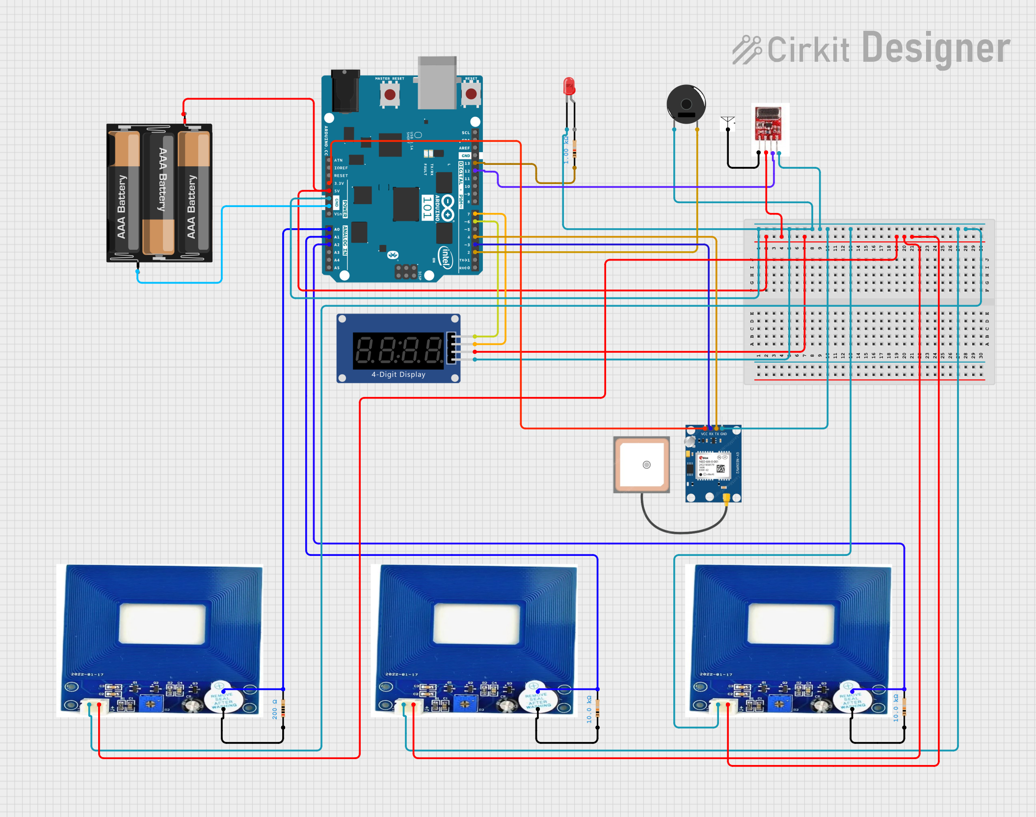
How to Use AC detector: Examples, Pinouts, and Specs

Image of AC detector
Cirkit Designer LogoDesign with AC detector in Cirkit Designer

Introduction

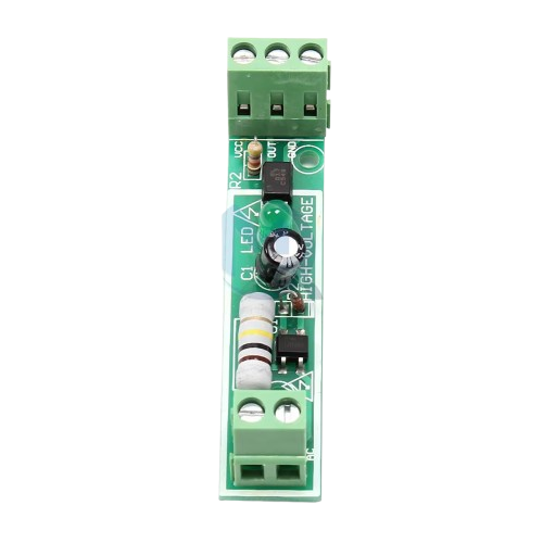
The AC Detector is a device designed to detect the presence of alternating current (AC) in a circuit. It is commonly used for safety and diagnostic purposes, allowing users to identify live wires and ensure that circuits are de-energized before performing maintenance or repairs. This component is essential for electricians, hobbyists, and engineers who work with AC-powered systems.

Explore Projects Built with AC detector

Use Cirkit Designer to design, explore, and prototype these projects online. Some projects support real-time simulation. Click "Open Project" to start designing instantly!
PIR Sensor-Activated Smart Light with Relay Control
Image of Motion Sensor Project: A project utilizing AC detector in a practical application
This circuit is a motion-activated AC bulb control system. It uses a PIR sensor to detect motion, which triggers a BC547 transistor to activate a KF-301 relay. The relay then controls the AC bulb, turning it on when motion is detected.
Cirkit Designer LogoOpen Project in Cirkit Designer
Arduino-Based Anti-Electric Shock Device with ACS712 Current Sensors and Relay Control
Image of Anti Electric shock Devise: A project utilizing AC detector in a practical application
This circuit is an anti-electric shock device that uses an Arduino UNO to monitor current through two ACS712 current sensors and control a 5V relay. The Arduino reads the current values from the sensors, compares them to predefined thresholds, and activates the relay to disconnect the load if an overcurrent condition is detected.
Cirkit Designer LogoOpen Project in Cirkit Designer
Arduino and GSM-Based Power Monitoring and Wi-Fi Controlled Lighting System
Image of light monitoring system: A project utilizing AC detector in a practical application
This circuit is designed to monitor voltage and current using ACS712 current sensors and voltage sensors, calculate power, and control lighting via relay modules. It features an Arduino Uno R3 for processing sensor data and executing control logic, which includes sending alerts via a GSM module (sim 800l) if power falls below a threshold and connecting to WiFi using an ESP8266 module. The circuit also includes a battery with a charging module (TP4056), a step-up boost converter, and multiple AC power supplies with circuit breakers for safety.
Cirkit Designer LogoOpen Project in Cirkit Designer
Arduino 101 Based Metal Detection and GPS Tracking System with RF Communication
Image of Transmission Ckt Diagram: A project utilizing AC detector in a practical application
This is a sensor-based monitoring system with an Arduino 101 microcontroller at its core, designed to detect metal, provide visual and audio alerts, transmit data wirelessly, and track GPS location. It is powered by a 3xAA battery pack and includes signal conditioning and current limiting components.
Cirkit Designer LogoOpen Project in Cirkit Designer

Explore Projects Built with AC detector

Use Cirkit Designer to design, explore, and prototype these projects online. Some projects support real-time simulation. Click "Open Project" to start designing instantly!
Image of Motion Sensor Project: A project utilizing AC detector in a practical application
PIR Sensor-Activated Smart Light with Relay Control
This circuit is a motion-activated AC bulb control system. It uses a PIR sensor to detect motion, which triggers a BC547 transistor to activate a KF-301 relay. The relay then controls the AC bulb, turning it on when motion is detected.
Cirkit Designer LogoOpen Project in Cirkit Designer
Image of Anti Electric shock Devise: A project utilizing AC detector in a practical application
Arduino-Based Anti-Electric Shock Device with ACS712 Current Sensors and Relay Control
This circuit is an anti-electric shock device that uses an Arduino UNO to monitor current through two ACS712 current sensors and control a 5V relay. The Arduino reads the current values from the sensors, compares them to predefined thresholds, and activates the relay to disconnect the load if an overcurrent condition is detected.
Cirkit Designer LogoOpen Project in Cirkit Designer
Image of light monitoring system: A project utilizing AC detector in a practical application
Arduino and GSM-Based Power Monitoring and Wi-Fi Controlled Lighting System
This circuit is designed to monitor voltage and current using ACS712 current sensors and voltage sensors, calculate power, and control lighting via relay modules. It features an Arduino Uno R3 for processing sensor data and executing control logic, which includes sending alerts via a GSM module (sim 800l) if power falls below a threshold and connecting to WiFi using an ESP8266 module. The circuit also includes a battery with a charging module (TP4056), a step-up boost converter, and multiple AC power supplies with circuit breakers for safety.
Cirkit Designer LogoOpen Project in Cirkit Designer
Image of Transmission Ckt Diagram: A project utilizing AC detector in a practical application
Arduino 101 Based Metal Detection and GPS Tracking System with RF Communication
This is a sensor-based monitoring system with an Arduino 101 microcontroller at its core, designed to detect metal, provide visual and audio alerts, transmit data wirelessly, and track GPS location. It is powered by a 3xAA battery pack and includes signal conditioning and current limiting components.
Cirkit Designer LogoOpen Project in Cirkit Designer

Technical Specifications

Key Technical Details

Parameter Value
Operating Voltage 3.3V - 5V
Detection Voltage 90V - 250V AC
Output Type Digital (High/Low)
Response Time < 100ms
Operating Temperature -10°C to 50°C
Dimensions 30mm x 20mm x 10mm

Pin Configuration and Descriptions

Pin Number Pin Name Description
1 VCC Power supply (3.3V - 5V)
2 GND Ground
3 OUT Digital output (High when AC is detected, Low otherwise)

Usage Instructions

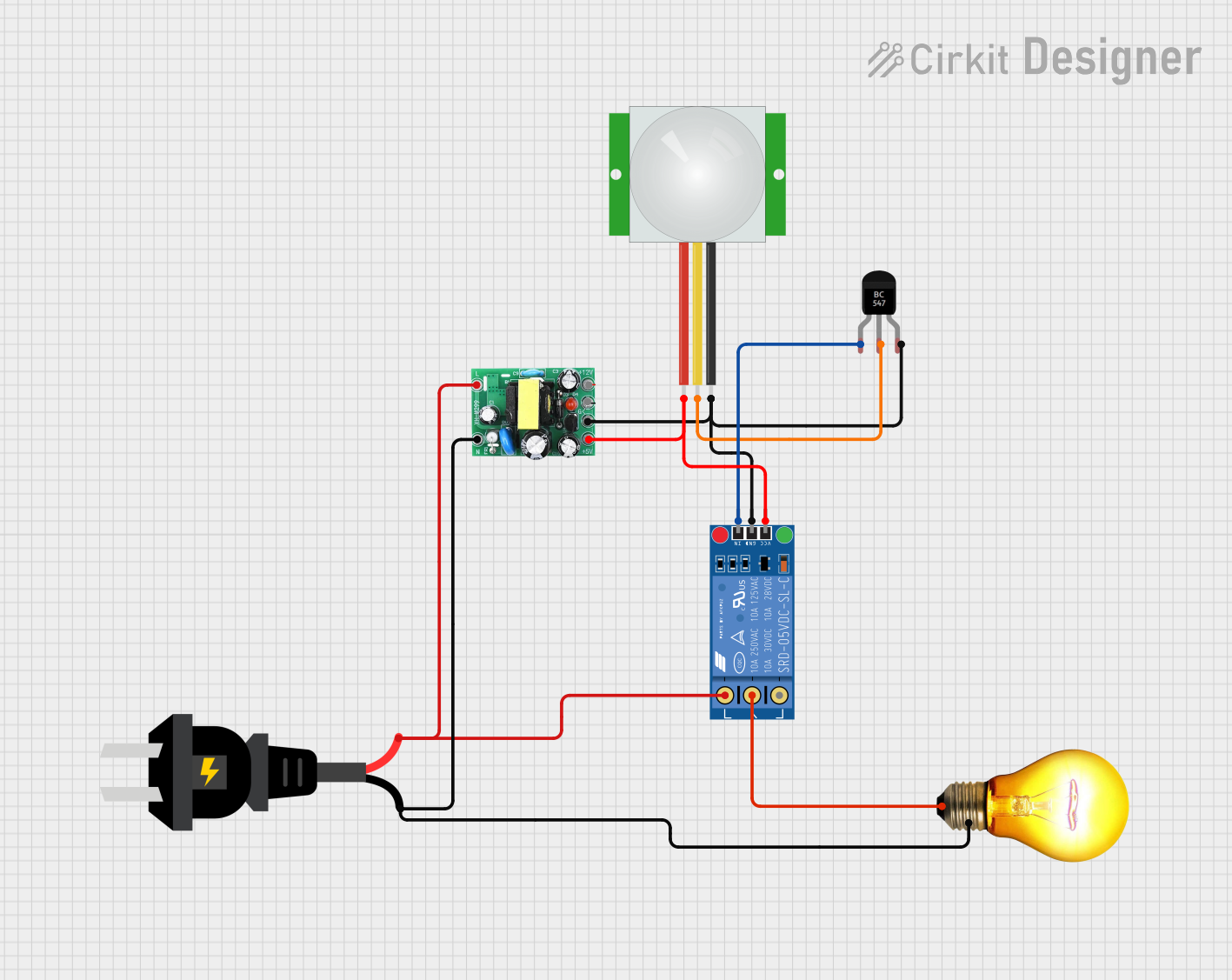
How to Use the Component in a Circuit

  1. Power Supply Connection: Connect the VCC pin to a 3.3V or 5V power supply and the GND pin to the ground of your circuit.
  2. Output Connection: Connect the OUT pin to a digital input pin of your microcontroller (e.g., Arduino UNO) to read the detection status.
  3. AC Detection: Place the AC Detector near the AC line or wire you want to test. The device will output a high signal when AC is detected and a low signal when no AC is present.

Important Considerations and Best Practices

  • Safety First: Always ensure that the AC Detector is used in a safe manner. Avoid direct contact with live AC wires.
  • Proper Placement: For accurate detection, place the AC Detector close to the AC source but avoid direct contact.
  • Power Supply: Ensure that the power supply voltage is within the specified range (3.3V - 5V) to avoid damaging the component.
  • Environmental Conditions: Use the AC Detector within the specified operating temperature range (-10°C to 50°C) for optimal performance.

Example Code for Arduino UNO

// Example code to use AC Detector with Arduino UNO

const int acDetectorPin = 2; // Digital pin connected to OUT pin of AC Detector
const int ledPin = 13;       // Onboard LED pin

void setup() {
  pinMode(acDetectorPin, INPUT); // Set acDetectorPin as input
  pinMode(ledPin, OUTPUT);       // Set ledPin as output
  Serial.begin(9600);            // Initialize serial communication
}

void loop() {
  int acStatus = digitalRead(acDetectorPin); // Read the status from AC Detector

  if (acStatus == HIGH) {
    digitalWrite(ledPin, HIGH); // Turn on LED if AC is detected
    Serial.println("AC Detected");
  } else {
    digitalWrite(ledPin, LOW);  // Turn off LED if no AC is detected
    Serial.println("No AC Detected");
  }

  delay(500); // Wait for 500 milliseconds before next reading
}

Troubleshooting and FAQs

Common Issues Users Might Face

  1. No Detection: The AC Detector does not detect AC even when placed near a live wire.

    • Solution: Ensure that the power supply voltage is correct and that the connections are secure. Verify that the AC voltage is within the detection range (90V - 250V AC).
  2. False Positives: The AC Detector indicates AC presence even when there is no AC.

    • Solution: Check for electromagnetic interference (EMI) from nearby devices. Ensure that the AC Detector is not placed near high-frequency devices or strong magnetic fields.
  3. Intermittent Detection: The AC Detector's output fluctuates between high and low.

    • Solution: Ensure stable placement of the AC Detector near the AC source. Verify that the power supply is stable and within the specified range.

Solutions and Tips for Troubleshooting

  • Check Connections: Ensure all connections are secure and correct.
  • Verify Power Supply: Make sure the power supply voltage is within the specified range (3.3V - 5V).
  • Avoid Interference: Keep the AC Detector away from sources of electromagnetic interference.
  • Stable Placement: Ensure the AC Detector is placed stably near the AC source for consistent detection.

By following this documentation, users can effectively utilize the AC Detector for their safety and diagnostic needs in AC-powered systems.