
How to Use GPS NEO 6M: Examples, Pinouts, and Specs
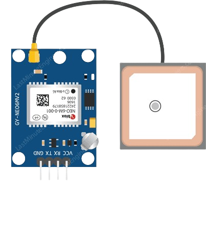
 Design with GPS NEO 6M in Cirkit Designer
Introduction
The GPS NEO 6M is a compact GPS receiver module designed to provide accurate positioning and timing information. It is widely used in applications such as robotics, drones, automotive systems, and IoT devices. Featuring high sensitivity, low power consumption, and reliable performance, the NEO 6M is an excellent choice for projects requiring precise location tracking and navigation.
Common applications include:
- Autonomous vehicles and drones
- Geographic mapping and surveying
- Real-time tracking systems
- Timing synchronization in IoT networks
Explore Projects Built with GPS NEO 6M
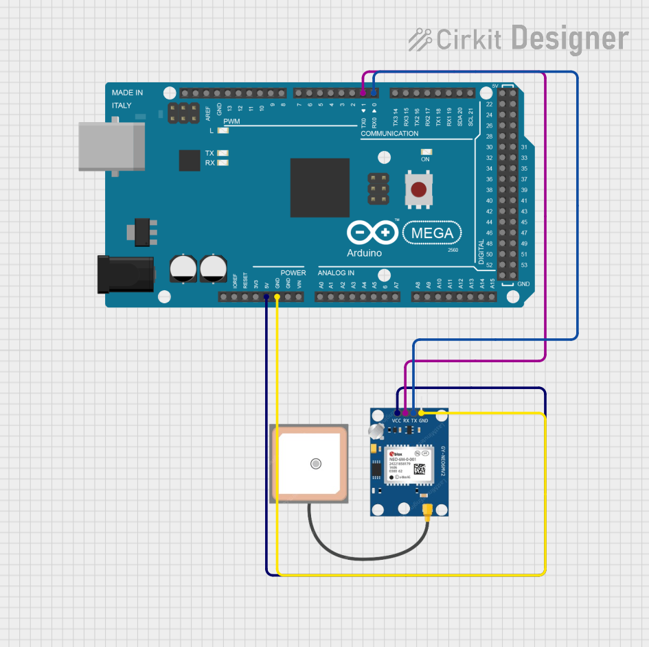 Open Project in Cirkit Designer
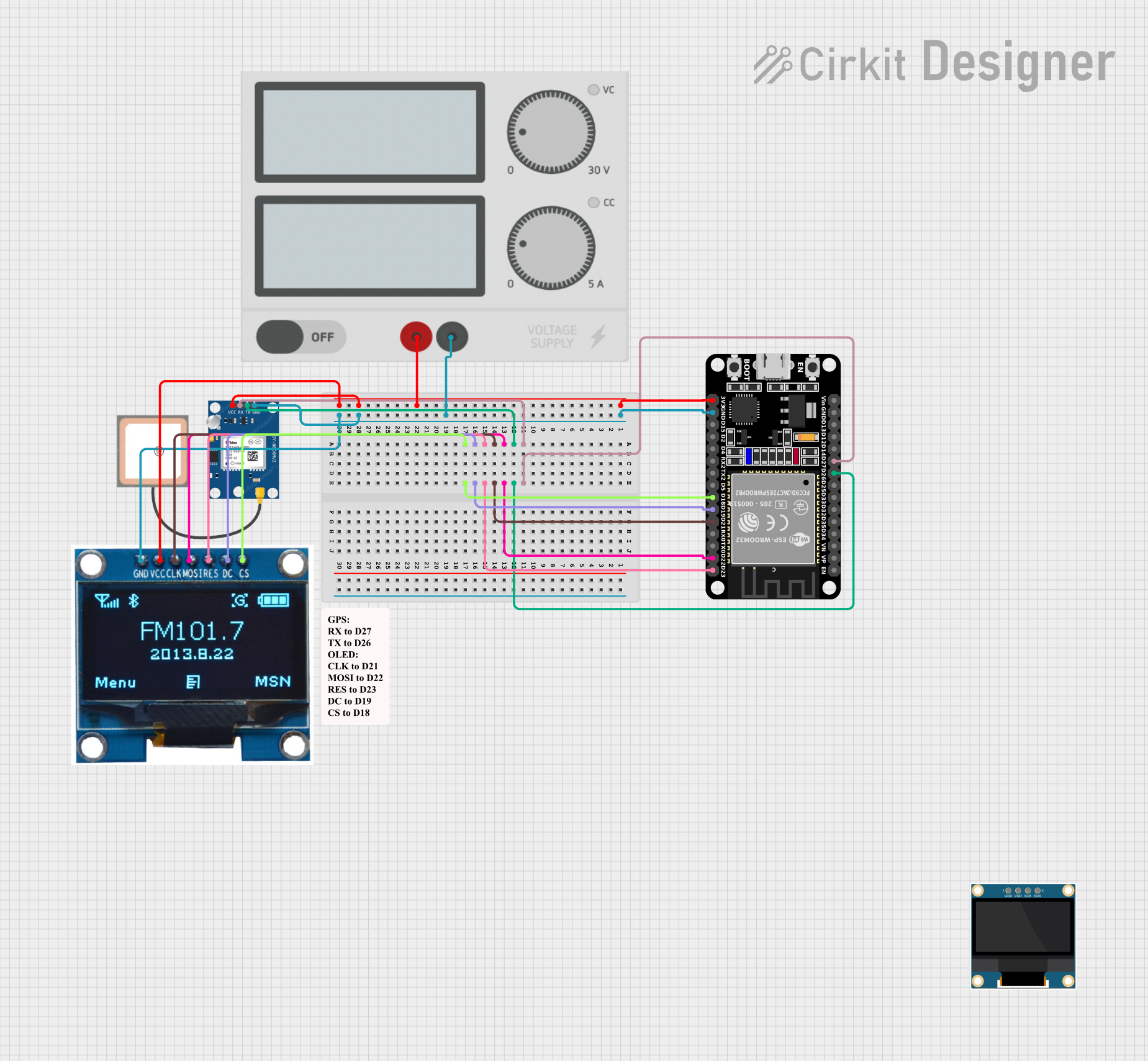 Open Project in Cirkit Designer
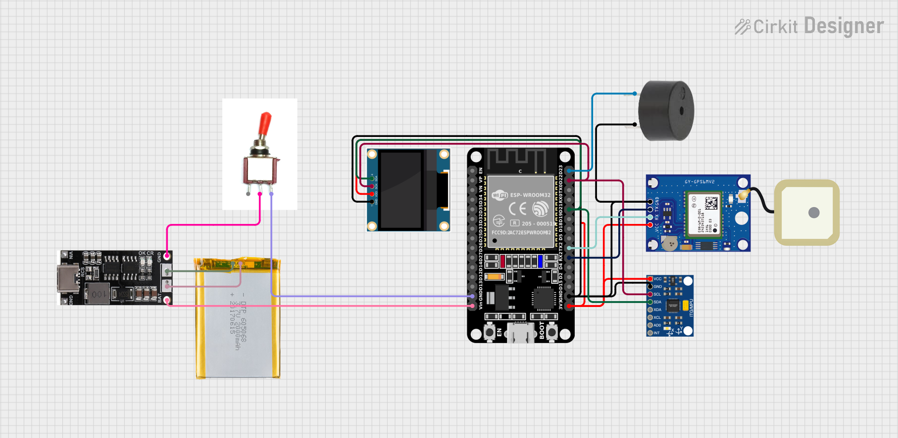 Open Project in Cirkit Designer
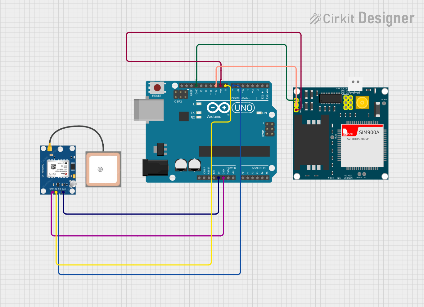 Open Project in Cirkit Designer
Explore Projects Built with GPS NEO 6M
Open Project in Cirkit DesignerOpen Project in Cirkit DesignerOpen Project in Cirkit DesignerOpen Project in Cirkit DesignerTechnical Specifications
The GPS NEO 6M module is built for versatility and ease of integration. Below are its key technical details:
General Specifications
| Parameter | Value |
|---|---|
| Operating Voltage | 3.3V to 5V |
| Power Consumption | ~45mA |
| Communication Protocol | UART (default), TTL level |
| Baud Rate (default) | 9600 bps |
| Position Accuracy | 2.5 meters CEP |
| Time to First Fix (TTFF) | Cold Start: 27s, Hot Start: 1s |
| Operating Temperature | -40°C to +85°C |
| Dimensions | 16 x 12.2 x 2.4 mm |
Pin Configuration
The GPS NEO 6M module typically comes with a 4-pin interface. Below is the pinout description:
| Pin Name | Pin Number | Description |
|---|---|---|
| VCC | 1 | Power supply input (3.3V to 5V) |
| GND | 2 | Ground connection |
| TX | 3 | UART Transmit pin (sends GPS data) |
| RX | 4 | UART Receive pin (receives configuration data) |
Usage Instructions
Connecting the GPS NEO 6M to a Circuit
- Power Supply: Connect the
VCCpin to a 3.3V or 5V power source and theGNDpin to ground. - UART Communication:
- Connect the
TXpin of the GPS module to theRXpin of your microcontroller (e.g., Arduino UNO). - Connect the
RXpin of the GPS module to theTXpin of your microcontroller.
- Connect the
- Antenna: Ensure the external antenna is securely connected to the module for optimal signal reception.
- LED Indicator: The onboard LED will blink to indicate GPS lock status:
- Blinking: Searching for satellites.
- Steady: GPS lock acquired.
Important Considerations
- Place the GPS module in an open area with minimal obstructions for better satellite reception.
- Avoid placing the module near high-frequency noise sources or metal surfaces that may interfere with the signal.
- Use a level shifter if interfacing with a 3.3V microcontroller to avoid damaging the module.
Example: Using GPS NEO 6M with Arduino UNO
Below is a sample Arduino sketch to read GPS data from the NEO 6M module:
#include <SoftwareSerial.h>

// Define RX and TX pins for SoftwareSerial
SoftwareSerial gpsSerial(4, 3); // RX = Pin 4, TX = Pin 3

void setup() {
  Serial.begin(9600);          // Initialize Serial Monitor at 9600 baud
  gpsSerial.begin(9600);       // Initialize GPS module at 9600 baud
  Serial.println("GPS NEO 6M Test");
}

void loop() {
  // Check if data is available from the GPS module
  while (gpsSerial.available()) {
    char gpsData = gpsSerial.read(); // Read one character from GPS
    Serial.print(gpsData);          // Print the character to Serial Monitor
  }
}
Code Explanation:
- The
SoftwareSeriallibrary is used to create a serial communication channel on pins 4 (RX) and 3 (TX). - The GPS module sends NMEA sentences (e.g.,
$GPGGA,$GPRMC) containing location and time data. - The sketch reads and displays the raw GPS data on the Serial Monitor.
Troubleshooting and FAQs
Common Issues
No GPS Lock (LED keeps blinking):
- Ensure the module is placed in an open area with a clear view of the sky.
- Check the antenna connection and ensure it is properly secured.
- Wait for a few minutes, as the first GPS lock (cold start) may take up to 27 seconds.
No Data Output on Serial Monitor:
- Verify the wiring between the GPS module and the microcontroller.
- Ensure the baud rate in the code matches the GPS module's default baud rate (9600 bps).
- Check if the correct pins are defined in the
SoftwareSerialsetup.
Garbage Data on Serial Monitor:
- Confirm that the Serial Monitor is set to the correct baud rate (9600 bps).
- Ensure proper grounding between the GPS module and the microcontroller.
FAQs
Q: Can the GPS NEO 6M work indoors?
A: While the module may work indoors near windows, its performance is significantly reduced. For best results, use it outdoors with a clear view of the sky.
Q: How can I improve GPS accuracy?
A: Use an active antenna for better signal reception and ensure the module is placed away from interference sources.
Q: Can I change the default baud rate?
A: Yes, the baud rate can be changed using specific configuration commands sent to the module. Refer to the NEO 6M datasheet for details.
Q: What is the maximum number of satellites the module can track?
A: The GPS NEO 6M can track up to 22 satellites simultaneously.
By following this documentation, you can effectively integrate and troubleshoot the GPS NEO 6M module in your projects.