How to Use buck-boost pwm input: Examples, Pinouts, and Specs
Introduction
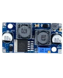
A buck-boost PWM input is a versatile power converter capable of stepping up (boosting) or stepping down (bucking) voltage levels. It uses pulse-width modulation (PWM) to regulate the output voltage and current efficiently. This component is widely used in applications where input voltage can vary above or below the desired output voltage, such as battery-powered devices, renewable energy systems, and automotive electronics.
Explore Projects Built with buck-boost pwm input
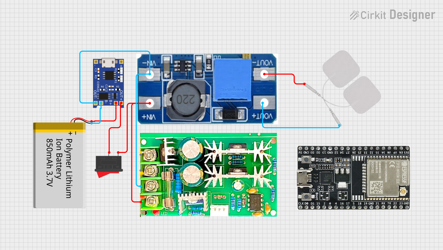
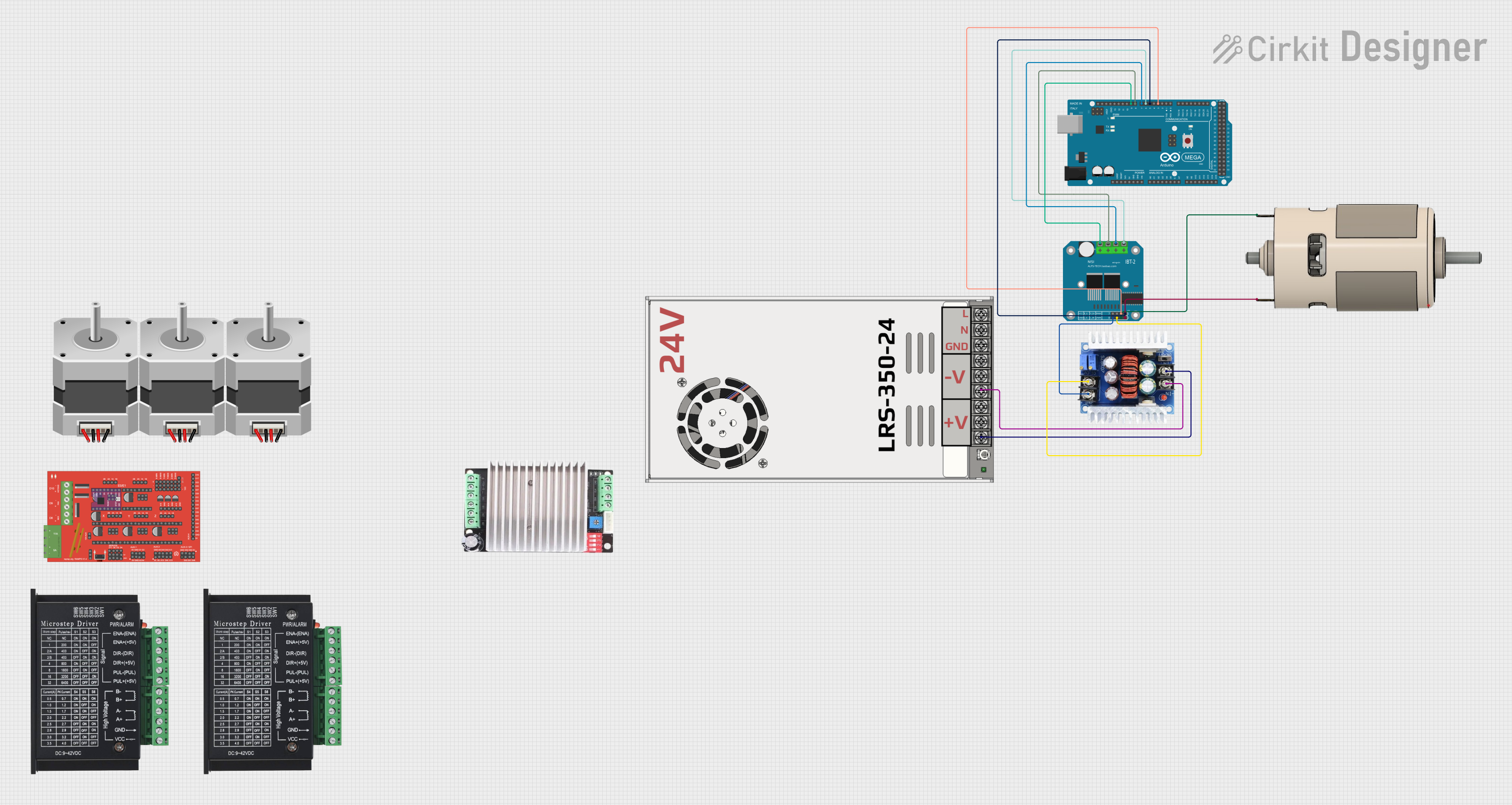

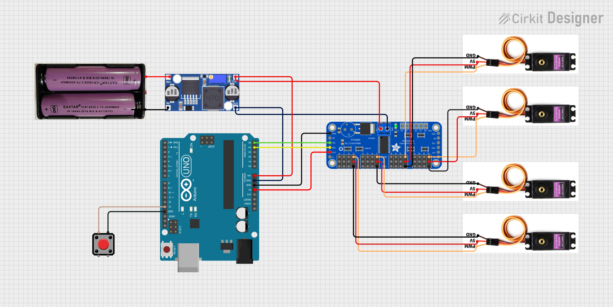
Explore Projects Built with buck-boost pwm input
Common Applications
- Battery-powered devices (e.g., portable electronics)
- Renewable energy systems (e.g., solar panels)
- Automotive electronics (e.g., LED lighting, infotainment systems)
- Industrial control systems
- Embedded systems requiring stable voltage regulation
Technical Specifications
Key Technical Details
| Parameter | Value/Range |
|---|---|
| Input Voltage Range | 3V to 36V |
| Output Voltage Range | 1.2V to 24V |
| Output Current | Up to 3A (depending on the model) |
| Efficiency | Up to 95% |
| Switching Frequency | 100 kHz to 1 MHz |
| Control Method | Pulse-Width Modulation (PWM) |
| Operating Temperature | -40°C to +85°C |
Pin Configuration and Descriptions
| Pin Name | Pin Number | Description |
|---|---|---|
| VIN | 1 | Input voltage pin. Connect to the power source (3V to 36V). |
| GND | 2 | Ground pin. Connect to the circuit ground. |
| VOUT | 3 | Output voltage pin. Provides the regulated voltage (1.2V to 24V). |
| EN | 4 | Enable pin. Logic HIGH enables the converter; logic LOW disables it. |
| PWM | 5 | PWM input pin. Used to control the output voltage and current. |
| FB | 6 | Feedback pin. Connect to a resistor divider to set the output voltage. |
| COMP | 7 | Compensation pin. Used for loop stability; connect to external components. |
| NC | 8 | No connection. Leave this pin unconnected. |
Usage Instructions
How to Use the Buck-Boost PWM Input in a Circuit
Connect the Input Voltage (VIN):
Attach the input voltage source (e.g., a battery or DC power supply) to the VIN pin. Ensure the input voltage is within the specified range (3V to 36V).Set the Output Voltage (VOUT):
Use a resistor divider connected to the FB pin to set the desired output voltage. Refer to the formula in the datasheet for calculating resistor values.Enable the Converter:
Drive the EN pin HIGH to enable the converter. If this pin is left floating, the converter may not operate correctly.Provide a PWM Signal:
Connect a PWM signal to the PWM pin to control the output voltage and current dynamically. The duty cycle of the PWM signal determines the output characteristics.Add External Components:
- Connect a suitable inductor and capacitor to the circuit for proper operation.
- Use the COMP pin to connect external components (e.g., capacitors) for loop stability.
Connect the Load:
Attach the load to the VOUT pin. Ensure the load does not exceed the maximum output current rating.
Important Considerations and Best Practices
- Inductor Selection: Choose an inductor with the appropriate current rating and inductance value to ensure efficient operation.
- Capacitor Selection: Use low-ESR capacitors for input and output filtering to minimize voltage ripple.
- Thermal Management: Ensure adequate heat dissipation, especially at high currents, to prevent overheating.
- PWM Signal Quality: Use a stable and noise-free PWM signal to avoid erratic output behavior.
- Startup Behavior: Verify that the input voltage is stable before enabling the converter to prevent damage.
Example: Using with an Arduino UNO
The buck-boost PWM input can be controlled using an Arduino UNO to generate the PWM signal. Below is an example code snippet:
// Example: Controlling a buck-boost converter with Arduino UNO
// This code generates a PWM signal on pin 9 to control the converter's output voltage.

const int pwmPin = 9; // PWM output pin connected to the PWM pin of the converter

void setup() {
  pinMode(pwmPin, OUTPUT); // Set the PWM pin as an output
}

void loop() {
  // Generate a PWM signal with a 50% duty cycle
  analogWrite(pwmPin, 128); // 128 corresponds to 50% duty cycle (0-255 scale)

  // Adjust the duty cycle as needed to control the output voltage
  delay(1000); // Wait for 1 second before making changes
}
Note: Adjust the analogWrite value to change the duty cycle and control the output voltage. Ensure the Arduino's PWM frequency is compatible with the converter's requirements.
Troubleshooting and FAQs
Common Issues and Solutions
No Output Voltage:
- Cause: The EN pin is not enabled.
Solution: Ensure the EN pin is driven HIGH or connected to VIN. - Cause: Incorrect resistor divider on the FB pin.
Solution: Verify the resistor values and connections.
- Cause: The EN pin is not enabled.
Excessive Voltage Ripple:
- Cause: Poor capacitor selection.
Solution: Use low-ESR capacitors with appropriate capacitance values. - Cause: Inadequate inductor value.
Solution: Select an inductor with the correct inductance and current rating.
- Cause: Poor capacitor selection.
Overheating:
- Cause: High current draw or poor thermal management.
Solution: Use a heatsink or improve airflow around the component.
- Cause: High current draw or poor thermal management.
Unstable Output Voltage:
- Cause: Improper compensation network.
Solution: Adjust the external components connected to the COMP pin.
- Cause: Improper compensation network.
FAQs
Q1: Can I use this converter with an input voltage lower than 3V?
A1: No, the input voltage must be within the specified range (3V to 36V) for proper operation.
Q2: How do I calculate the resistor values for the FB pin?
A2: Refer to the formula in the datasheet:
[
V_{OUT} = V_{REF} \times \left(1 + \frac{R1}{R2}\right)
]
where ( V_{REF} ) is the reference voltage, and ( R1 ) and ( R2 ) are the resistor values.
Q3: Can I leave the PWM pin unconnected?
A3: No, the PWM pin must receive a valid signal to control the output voltage and current.
Q4: What happens if the load exceeds the maximum current rating?
A4: The converter may enter overcurrent protection mode or shut down to prevent damage. Always ensure the load is within the specified limits.