How to Use Tri-Stimulus XYZ Color, Temperature and Lux Sensor: Examples, Pinouts, and Specs
Introduction
The Adafruit OPT4048 Tri-Stimulus XYZ Color, Temperature, and Lux Sensor is a highly accurate and versatile sensor designed to measure color, light intensity (lux), and correlated color temperature (CCT). It is based on the XYZ color space model, which closely mimics human vision, making it ideal for applications requiring precise color and light measurements.
This sensor is widely used in applications such as:
- Display calibration and color management
- Ambient light sensing for smart lighting systems
- Industrial color quality control
- Photography and cinematography lighting adjustments
- Environmental monitoring
Explore Projects Built with Tri-Stimulus XYZ Color, Temperature and Lux Sensor
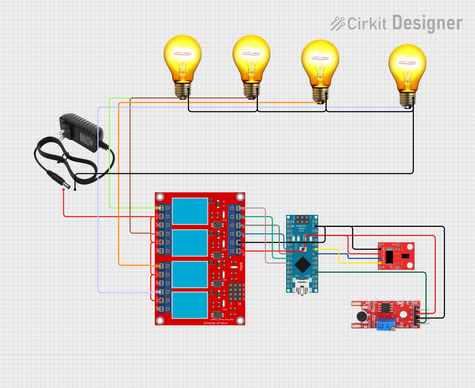
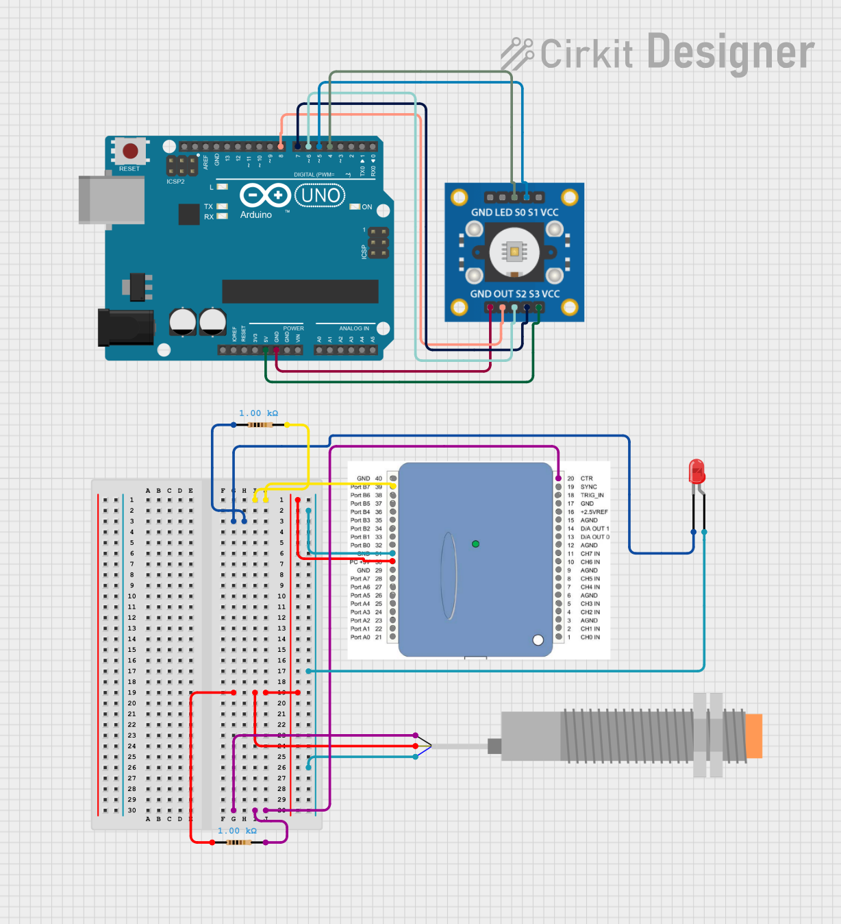
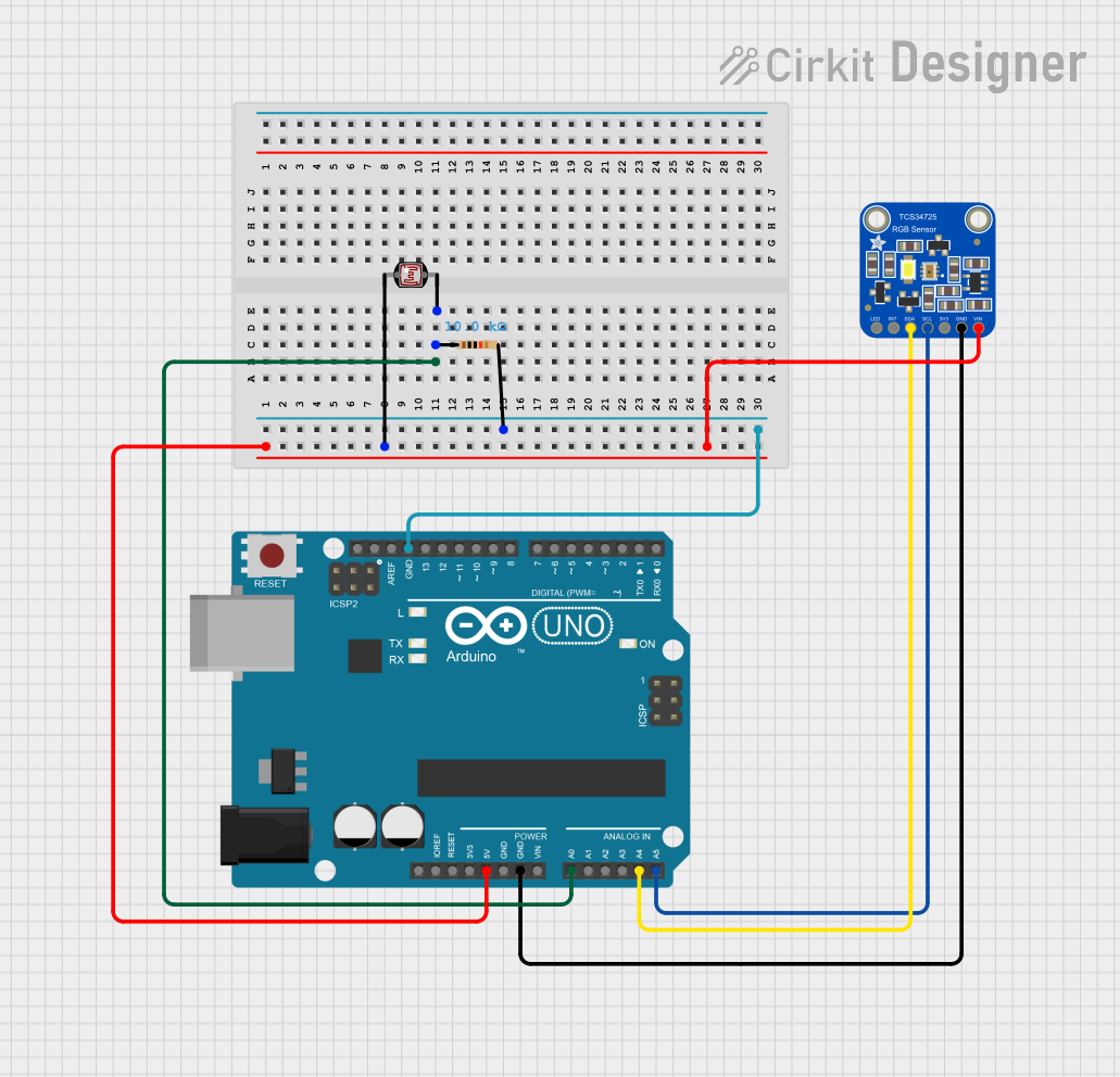

Explore Projects Built with Tri-Stimulus XYZ Color, Temperature and Lux Sensor
Technical Specifications
The following table outlines the key technical details of the Adafruit OPT4048 sensor:
| Parameter | Value |
|---|---|
| Manufacturer Part ID | OPT4048 |
| Operating Voltage | 3.3V to 5V |
| Communication Interface | I2C |
| Measurement Range (Lux) | 0.01 lux to 83,000 lux |
| Correlated Color Temperature | 1,000K to 40,000K |
| Color Measurement | XYZ tristimulus values |
| Operating Temperature Range | -40°C to +85°C |
| Power Consumption | ~1.5 mA (active mode) |
Pin Configuration and Descriptions
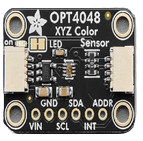
The OPT4048 sensor module typically comes with the following pinout:
| Pin Name | Description |
|---|---|
| VIN | Power input (3.3V to 5V) |
| GND | Ground connection |
| SCL | I2C clock line (connect to Arduino's A5 or dedicated SCL pin) |
| SDA | I2C data line (connect to Arduino's A4 or dedicated SDA pin) |
| INT | Interrupt pin (optional, used for event-driven applications) |
| ADDR | I2C address selection pin (connect to GND or leave floating for default address) |
Usage Instructions
How to Use the OPT4048 in a Circuit
- Power the Sensor: Connect the VIN pin to a 3.3V or 5V power source and the GND pin to ground.
- I2C Communication: Connect the SDA and SCL pins to the corresponding I2C pins on your microcontroller (e.g., Arduino UNO).
- Optional Interrupt: If you need event-driven notifications, connect the INT pin to a digital input pin on your microcontroller.
- I2C Address Selection: Leave the ADDR pin floating or connect it to GND to use the default I2C address (0x39).
Important Considerations and Best Practices
- Pull-Up Resistors: Ensure that the I2C lines (SDA and SCL) have appropriate pull-up resistors (typically 4.7kΩ). Many breakout boards include these resistors by default.
- Ambient Light Interference: Avoid placing the sensor in direct sunlight or near strong light sources unless these are part of the intended measurement environment.
- Calibration: For critical applications, consider calibrating the sensor using a known light source or color reference.
Example Code for Arduino UNO
Below is an example Arduino sketch to read XYZ color values, lux, and CCT from the OPT4048 sensor:
#include <Wire.h>
#include <Adafruit_Sensor.h>
#include <Adafruit_OPT4048.h>

// Create an instance of the OPT4048 sensor
Adafruit_OPT4048 opt4048;

void setup() {
  Serial.begin(9600); // Initialize serial communication
  while (!Serial) delay(10); // Wait for Serial Monitor to open

  // Initialize I2C communication and the sensor
  if (!opt4048.begin()) {
    Serial.println("Failed to find OPT4048 sensor! Check wiring.");
    while (1) delay(10); // Halt execution if sensor is not found
  }
  Serial.println("OPT4048 sensor initialized.");
}

void loop() {
  // Read XYZ tristimulus values
  float x, y, z;
  opt4048.getXYZ(&x, &y, &z);

  // Read lux and correlated color temperature (CCT)
  float lux = opt4048.getLux();
  float cct = opt4048.getCCT();

  // Print the results to the Serial Monitor
  Serial.print("X: "); Serial.print(x);
  Serial.print(" Y: "); Serial.print(y);
  Serial.print(" Z: "); Serial.print(z);
  Serial.print(" Lux: "); Serial.print(lux);
  Serial.print(" CCT: "); Serial.print(cct);
  Serial.println(" K");

  delay(1000); // Wait 1 second before the next reading
}
Troubleshooting and FAQs
Common Issues and Solutions
Sensor Not Detected
- Cause: Incorrect wiring or I2C address mismatch.
- Solution: Double-check the connections and ensure the ADDR pin is configured correctly. Use an I2C scanner sketch to verify the sensor's address.
Inaccurate Readings
- Cause: Ambient light interference or improper placement.
- Solution: Shield the sensor from unwanted light sources and ensure it is positioned correctly for the intended measurement.
No Data Output
- Cause: Missing or incorrect library installation.
- Solution: Ensure the Adafruit_OPT4048 library is installed in your Arduino IDE. You can install it via the Library Manager.
FAQs
Q: Can the OPT4048 measure UV or IR light?
A: No, the OPT4048 is designed to measure visible light in the XYZ color space and does not detect UV or IR wavelengths.
Q: What is the default I2C address of the OPT4048?
A: The default I2C address is 0x39. You can verify this using an I2C scanner sketch.
Q: Can I use the OPT4048 with a 3.3V microcontroller?
A: Yes, the sensor is compatible with both 3.3V and 5V logic levels.
Q: How do I improve measurement accuracy?
A: For best results, calibrate the sensor using a known light source and minimize ambient light interference.
This documentation provides a comprehensive guide to using the Adafruit OPT4048 sensor effectively. For further assistance, refer to the Adafruit support forums or the sensor's datasheet.