Cirkit Designer Logo
Cirkit Designer
Your all-in-one circuit design IDE
Home / 
Component Documentation

How to Use SparkFun Large Digit Driver: Examples, Pinouts, and Specs

Image of SparkFun Large Digit Driver
Cirkit Designer LogoDesign with SparkFun Large Digit Driver in Cirkit Designer

Introduction

The SparkFun Large Digit Driver is an innovative module designed to control large 7-segment LED displays. This driver is versatile, supporting both common cathode and common anode displays, and can be interfaced using Serial Peripheral Interface (SPI) or a parallel connection. It is ideal for creating digital timers, clocks, counters, or any project that requires a big, bright, and easy-to-read display.

Explore Projects Built with SparkFun Large Digit Driver

Use Cirkit Designer to design, explore, and prototype these projects online. Some projects support real-time simulation. Click "Open Project" to start designing instantly!
Arduino UNO Controlled Obstacle Avoiding Robot with L293D Motor Driver and Ultrasonic Sensor
Image of wall e: A project utilizing SparkFun Large Digit Driver in a practical application
This circuit is designed to control a robot with four DC motors for movement, an ultrasonic sensor for distance measurement, and a servo motor to direct the sensor. The L293D driver shield interfaces with the motors, while the Arduino UNO microcontroller runs the embedded code to process sensor data and control motor speeds and directions. An LCD display is included for output, and power is supplied by a 4 x AAA battery mount.
Cirkit Designer LogoOpen Project in Cirkit Designer
Arduino UNO-Based Dual Stepper Motor Controller with Gesture Sensing and RTC Display
Image of Arduino UNO-Based Dual Stepper Motor Controller with Gesture Sensing and RTC Display: A project utilizing SparkFun Large Digit Driver in a practical application
This circuit is an Arduino UNO-based dual stepper motor controller that uses ULN2003A driver boards to control two 28BYJ-48 stepper motors. It features an APDS-9960 RGB and gesture sensor for gesture-based control, a DS1307 RTC module to display time on a 16x2 I2C LCD, and includes a green LED and two pushbuttons for additional control and status indication.
Cirkit Designer LogoOpen Project in Cirkit Designer
Arduino-Controlled Interactive LED and Sound System with Motion Detection
Image of project 1: A project utilizing SparkFun Large Digit Driver in a practical application
This circuit features an Arduino UNO microcontroller interfaced with an Adafruit ADXL345 accelerometer, an HC-SR04 ultrasonic sensor, two SG90 servomotors, a DFPlayer Mini MP3 module, a WS2812 RGB LED strip, and a loudspeaker. The Arduino controls the LED strip and servomotors based on distance measurements from the ultrasonic sensor and plays sounds through the DFPlayer Mini when motion is detected by the accelerometer. The circuit is designed for interactive displays or installations where visual and auditory feedback is provided in response to object proximity and movement.
Cirkit Designer LogoOpen Project in Cirkit Designer
Arduino Mega 2560-Based Smart Sensor System with IR Sensors, LCD Display, and Stepper Motor Control
Image of temple: A project utilizing SparkFun Large Digit Driver in a practical application
This circuit uses an Arduino Mega 2560 to interface with multiple IR sensors, a force-sensitive resistor, a piezo buzzer, a 16x2 I2C LCD, and a stepper motor controlled by an Adafruit TB6612 motor driver. The system is designed to detect inputs from the sensors and display information on the LCD while controlling the buzzer and stepper motor based on the sensor readings.
Cirkit Designer LogoOpen Project in Cirkit Designer

Explore Projects Built with SparkFun Large Digit Driver

Use Cirkit Designer to design, explore, and prototype these projects online. Some projects support real-time simulation. Click "Open Project" to start designing instantly!
Image of wall e: A project utilizing SparkFun Large Digit Driver in a practical application
Arduino UNO Controlled Obstacle Avoiding Robot with L293D Motor Driver and Ultrasonic Sensor
This circuit is designed to control a robot with four DC motors for movement, an ultrasonic sensor for distance measurement, and a servo motor to direct the sensor. The L293D driver shield interfaces with the motors, while the Arduino UNO microcontroller runs the embedded code to process sensor data and control motor speeds and directions. An LCD display is included for output, and power is supplied by a 4 x AAA battery mount.
Cirkit Designer LogoOpen Project in Cirkit Designer
Image of Arduino UNO-Based Dual Stepper Motor Controller with Gesture Sensing and RTC Display: A project utilizing SparkFun Large Digit Driver in a practical application
Arduino UNO-Based Dual Stepper Motor Controller with Gesture Sensing and RTC Display
This circuit is an Arduino UNO-based dual stepper motor controller that uses ULN2003A driver boards to control two 28BYJ-48 stepper motors. It features an APDS-9960 RGB and gesture sensor for gesture-based control, a DS1307 RTC module to display time on a 16x2 I2C LCD, and includes a green LED and two pushbuttons for additional control and status indication.
Cirkit Designer LogoOpen Project in Cirkit Designer
Image of project 1: A project utilizing SparkFun Large Digit Driver in a practical application
Arduino-Controlled Interactive LED and Sound System with Motion Detection
This circuit features an Arduino UNO microcontroller interfaced with an Adafruit ADXL345 accelerometer, an HC-SR04 ultrasonic sensor, two SG90 servomotors, a DFPlayer Mini MP3 module, a WS2812 RGB LED strip, and a loudspeaker. The Arduino controls the LED strip and servomotors based on distance measurements from the ultrasonic sensor and plays sounds through the DFPlayer Mini when motion is detected by the accelerometer. The circuit is designed for interactive displays or installations where visual and auditory feedback is provided in response to object proximity and movement.
Cirkit Designer LogoOpen Project in Cirkit Designer
Image of temple: A project utilizing SparkFun Large Digit Driver in a practical application
Arduino Mega 2560-Based Smart Sensor System with IR Sensors, LCD Display, and Stepper Motor Control
This circuit uses an Arduino Mega 2560 to interface with multiple IR sensors, a force-sensitive resistor, a piezo buzzer, a 16x2 I2C LCD, and a stepper motor controlled by an Adafruit TB6612 motor driver. The system is designed to detect inputs from the sensors and display information on the LCD while controlling the buzzer and stepper motor based on the sensor readings.
Cirkit Designer LogoOpen Project in Cirkit Designer

Common Applications and Use Cases

  • Digital clocks and timers
  • Scoreboards for sports events
  • Event counters
  • Public information displays
  • Custom large-scale digital readouts

Technical Specifications

Key Technical Details

  • Operating Voltage: 3.3V to 5.5V
  • Max Current per Segment: 200mA
  • Max Current per Digit: 1.4A (assuming 7 segments on at 200mA each)
  • Display Support: Common anode or common cathode 7-segment displays
  • Interface: SPI or parallel
  • Daisy Chainable: Yes

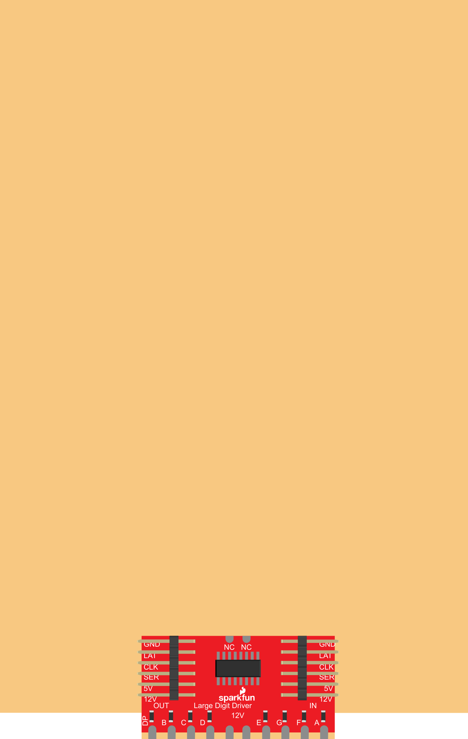
Pin Configuration and Descriptions

Pin Number Name Description
1 VCC Power supply (3.3V to 5.5V)
2 GND Ground connection
3 LAT Latch pin, controls when data is latched into the display
4 CLK Clock pin, used for SPI clock
5 SER Serial data input, used for SPI data
6 OE Output enable, active low
7-14 SEG A-G, DP Segment control pins for direct drive (parallel interface)
15-22 DIG 1-8 Digit control pins for direct drive (parallel interface)

Usage Instructions

How to Use the Component in a Circuit

  1. Powering the Driver: Connect VCC to a 3.3V or 5V power supply and GND to the ground.

  2. Connecting the Display: Attach the segments of the 7-segment display to the SEG A-G and DP pins. Connect the common anode or cathode of the display to the respective power supply or ground.

  3. Interfacing with a Microcontroller:

    • For SPI, connect LAT, CLK, and SER to the corresponding pins on your microcontroller.
    • For parallel, connect SEG and DIG pins directly to the microcontroller's GPIO pins.
  4. Programming the Microcontroller: Write or upload the appropriate code to drive the display via SPI or parallel interface.

Important Considerations and Best Practices

  • Ensure that the power supply voltage matches the operating voltage of the Large Digit Driver.
  • Be mindful of the current requirements, especially if all segments are lit simultaneously.
  • Use current-limiting resistors with each segment to prevent damage to the LEDs.
  • When daisy-chaining multiple drivers, ensure that the power supply can handle the cumulative current draw.
  • For SPI communication, ensure that the microcontroller's SPI settings (clock polarity, phase, and speed) match the driver's requirements.

Troubleshooting and FAQs

Common Issues Users Might Face

  • Display Not Lighting Up: Check the power supply connections and the common anode/cathode connection to ensure they are correct.
  • Segments Flickering or Dim: Verify that the current-limiting resistors are appropriate and that the power supply can handle the current draw.
  • Incorrect Display Output: Double-check the wiring and ensure that the SPI or parallel data being sent matches the expected format.

Solutions and Tips for Troubleshooting

  • Always start with a single digit and segment to ensure your setup is working before expanding to more digits or segments.
  • Use a multimeter to verify connections and voltages at various points in the circuit.
  • If using SPI, use a logic analyzer or oscilloscope to check the data signals for correct timing and values.

FAQs

Q: Can I use the Large Digit Driver with a 3.3V system? A: Yes, the driver operates from 3.3V to 5.5V.

Q: How many digits can I daisy-chain together? A: You can daisy-chain multiple drivers, but the limit depends on your power supply's capacity and the microcontroller's ability to drive the signals over a longer distance.

Q: Can I control the brightness of the display? A: Yes, you can control the brightness by using PWM on the OE pin or by adjusting the current-limiting resistors.

Example Code for Arduino UNO

// Example code for driving a single digit 7-segment display using the SparkFun Large Digit Driver

#include <SPI.h>

// Define the pins
const int latchPin = 5; // LAT pin
const int clockPin = 13; // CLK pin
const int dataPin = 11; // SER pin

void setup() {
  // Set pins to output
  pinMode(latchPin, OUTPUT);
  pinMode(clockPin, OUTPUT);
  pinMode(dataPin, OUTPUT);

  // Initialize SPI
  SPI.begin();
  SPI.setClockDivider(SPI_CLOCK_DIV128); // Adjust as necessary
}

void loop() {
  // Example: Display the number '1'
  byte segments = B00000110; // Define the segments for the number '1'

  // Begin SPI transaction
  digitalWrite(latchPin, LOW);
  SPI.transfer(segments);
  digitalWrite(latchPin, HIGH);

  // Pause for clarity
  delay(1000);
}

This example demonstrates how to send data to a single digit of the 7-segment display using SPI. The segments byte should be changed according to the number or character you wish to display. The SPI clock divider may need to be adjusted based on your specific microcontroller's clock speed.