How to Use LCD 12C : Examples, Pinouts, and Specs
Introduction
The LCD I2C is a Liquid Crystal Display module that communicates using the I2C (Inter-Integrated Circuit) protocol. This module simplifies the process of connecting an LCD to microcontrollers by reducing the number of required pins. It is widely used for displaying text, numbers, and simple graphics in embedded systems and DIY electronics projects.
Explore Projects Built with LCD 12C
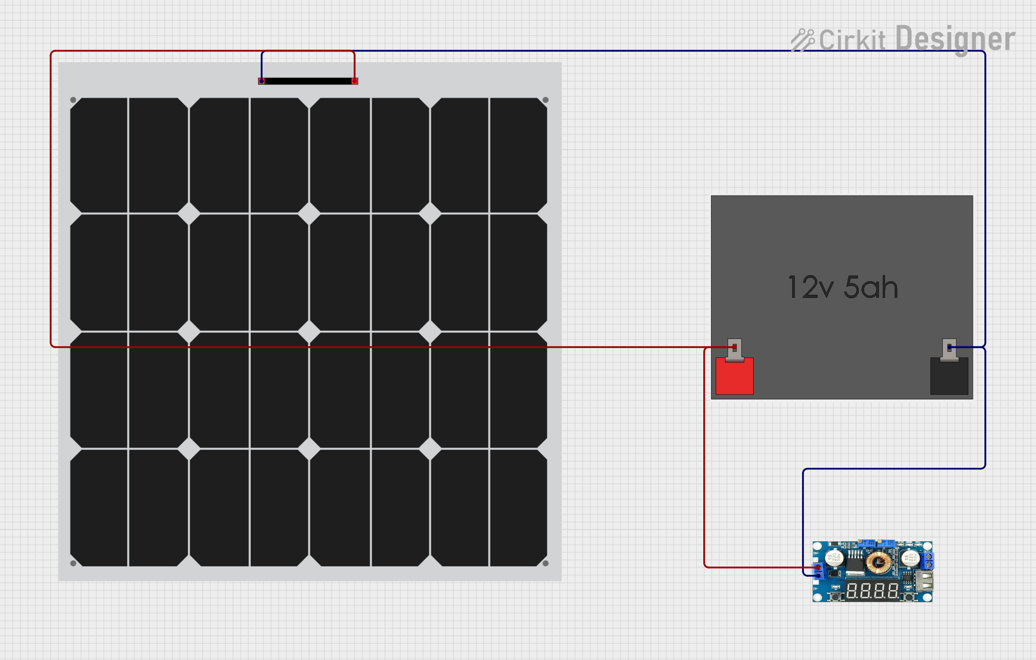
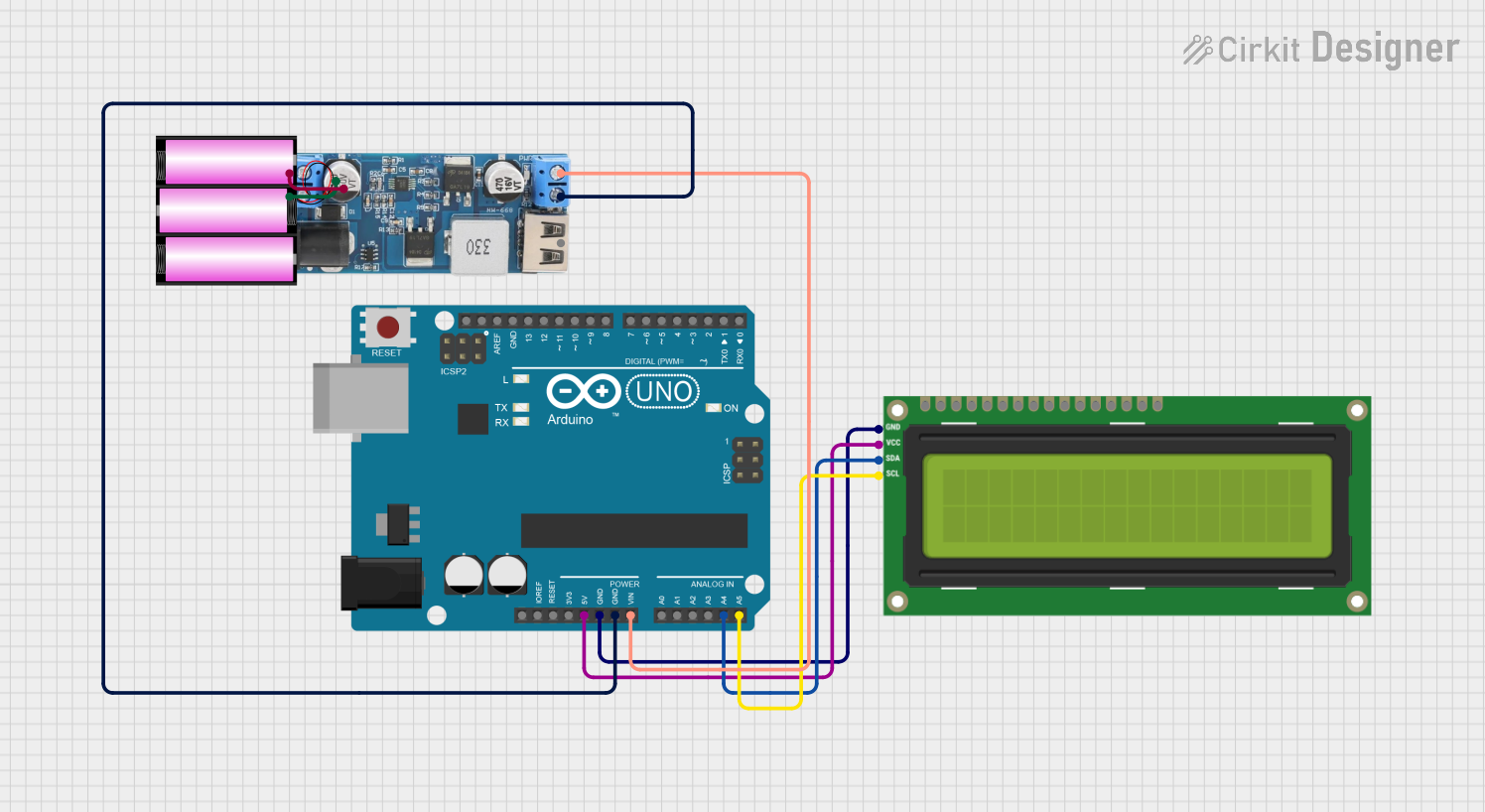


Explore Projects Built with LCD 12C
Common Applications and Use Cases
- Microcontroller-based projects (e.g., Arduino, Raspberry Pi)
- User interfaces for embedded systems
- Real-time data display (e.g., temperature, humidity, sensor readings)
- Educational and prototyping purposes
- Home automation systems
Technical Specifications
Key Technical Details
- Display Type: 16x2 or 20x4 character LCD (varies by model)
- Communication Protocol: I2C
- Operating Voltage: 5V DC
- Backlight: LED with adjustable brightness
- I2C Address: Typically 0x27 or 0x3F (configurable)
- Current Consumption: ~20mA (with backlight on)
- Contrast Adjustment: Via onboard potentiometer
Pin Configuration and Descriptions
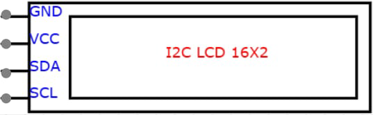
The LCD I2C module has a 4-pin interface for I2C communication. Below is the pinout:
| Pin | Name | Description |
|---|---|---|
| 1 | GND | Ground (0V) |
| 2 | VCC | Power supply (5V DC) |
| 3 | SDA | Serial Data Line for I2C communication |
| 4 | SCL | Serial Clock Line for I2C communication |
Usage Instructions
How to Use the LCD I2C in a Circuit
Connect the Module:
- Connect the
GNDpin to the ground of your microcontroller. - Connect the
VCCpin to the 5V power supply of your microcontroller. - Connect the
SDApin to the I2C data line (e.g., A4 on Arduino UNO). - Connect the
SCLpin to the I2C clock line (e.g., A5 on Arduino UNO).
- Connect the
Install Required Libraries:
- For Arduino, install the
LiquidCrystal_I2Clibrary via the Library Manager in the Arduino IDE.
- For Arduino, install the
Write and Upload Code:
- Use the following example code to display text on the LCD:
#include <Wire.h>
#include <LiquidCrystal_I2C.h>

// Initialize the LCD with I2C address 0x27 and a 16x2 display size
LiquidCrystal_I2C lcd(0x27, 16, 2);

void setup() {
  lcd.begin(); // Initialize the LCD
  lcd.backlight(); // Turn on the backlight
  lcd.setCursor(0, 0); // Set cursor to the first row, first column
  lcd.print("Hello, World!"); // Display text on the LCD
  lcd.setCursor(0, 1); // Move to the second row
  lcd.print("I2C LCD Module"); // Display additional text
}

void loop() {
  // No actions in the loop for this example
}
Important Considerations and Best Practices
- I2C Address: Ensure the correct I2C address is used in your code. If unsure, use an I2C scanner sketch to detect the address.
- Power Supply: Use a stable 5V power source to avoid flickering or malfunction.
- Contrast Adjustment: Use the onboard potentiometer to adjust the display contrast for optimal visibility.
- Pull-Up Resistors: Some I2C setups may require external pull-up resistors on the SDA and SCL lines if not already included on the module.
Troubleshooting and FAQs
Common Issues and Solutions
LCD Not Displaying Anything:
- Verify all connections are secure and correct.
- Check the I2C address in your code. Use an I2C scanner to confirm the address.
- Adjust the contrast potentiometer on the module.
Flickering or Unstable Display:
- Ensure the power supply provides a stable 5V.
- Check for loose or poor connections.
Backlight Not Turning On:
- Confirm the
lcd.backlight()function is called in your code. - Check the power connections to the module.
- Confirm the
Text Not Displaying Correctly:
- Ensure the correct display size (e.g., 16x2 or 20x4) is specified in the code.
- Verify the I2C address and connections.
FAQs
Q: How do I find the I2C address of my LCD module?
A: Use an I2C scanner sketch to detect the address. This sketch scans all possible I2C addresses and prints the detected address to the Serial Monitor.
Q: Can I use the LCD I2C module with a 3.3V microcontroller?
A: Yes, but ensure the module is compatible with 3.3V logic levels or use a level shifter.
Q: Can I connect multiple I2C devices to the same microcontroller?
A: Yes, as long as each device has a unique I2C address. If two devices share the same address, you may need to modify one device's address (if possible).
Q: How do I display custom characters on the LCD?
A: Use the createChar() function in the LiquidCrystal_I2C library to define and display custom characters.
By following this documentation, you can effectively integrate and troubleshoot the LCD I2C module in your projects.