The IRLZ44N is an N-channel MOSFET (Metal-Oxide-Semiconductor Field-Effect Transistor) designed for high-speed switching applications. It features a low on-resistance (RDS(on)), enabling it to handle high currents efficiently with minimal power loss. This makes the IRLZ44N an excellent choice for power management, motor control, LED drivers, and other high-current applications. Its logic-level gate drive capability allows it to be directly controlled by microcontrollers like the Arduino UNO, making it a popular component in DIY electronics and industrial designs.
Explore Projects Built with IRLZ44N
Use Cirkit Designer to design, explore, and prototype these projects online. Some projects support real-time simulation. Click "Open Project" to start designing instantly!
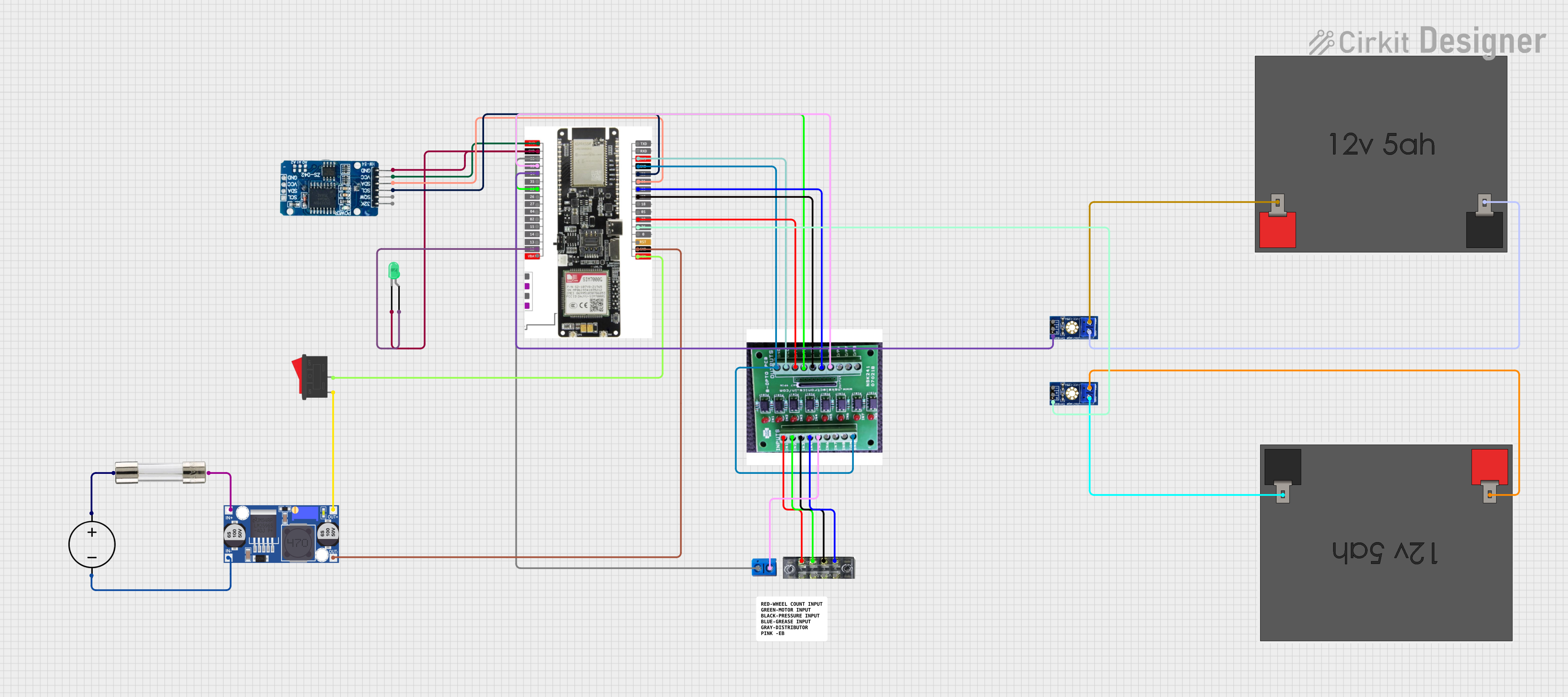
This circuit features a LilyGo-SIM7000G module for cellular communication and GPS functionality, interfaced with an RTC DS3231 for real-time clock capabilities. It includes voltage sensing through two voltage sensor modules, and uses an 8-channel opto-coupler for isolating different parts of the circuit. Power management is handled by a buck converter connected to a DC power source and batteries, with a fuse for protection and a rocker switch for on/off control. Additionally, there's an LED for indication purposes.
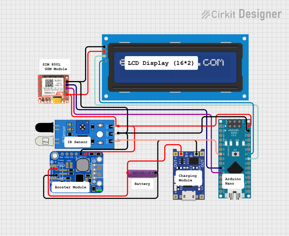
This circuit is designed to interface an Arduino Nano with an IR sensor for input, a SIM800L module for GSM communication, and an I2C LCD screen for output display. It includes a 3.7V battery with a TP4056 charging module and a PowerBoost 1000 Basic for power management. The Arduino's code is currently a placeholder, suggesting that the user-defined functionality is pending.
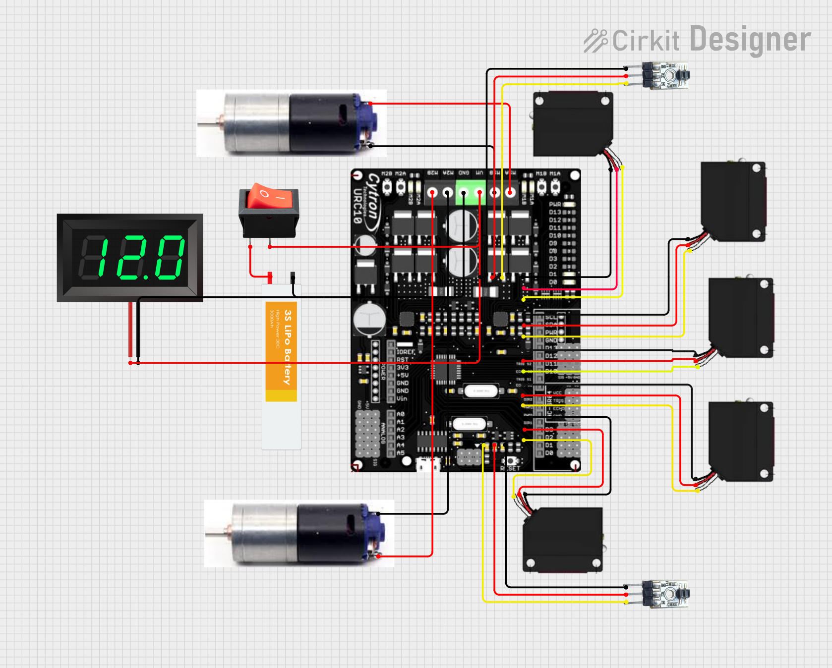
This circuit is a robotic control system that uses multiple IR sensors for line detection and obstacle avoidance, powered by a 3S LiPo battery. The Cytron URC10 motor driver, controlled by a microcontroller, drives two GM25 DC motors based on input from the sensors and a rocker switch, with a 7-segment panel voltmeter displaying the battery voltage.
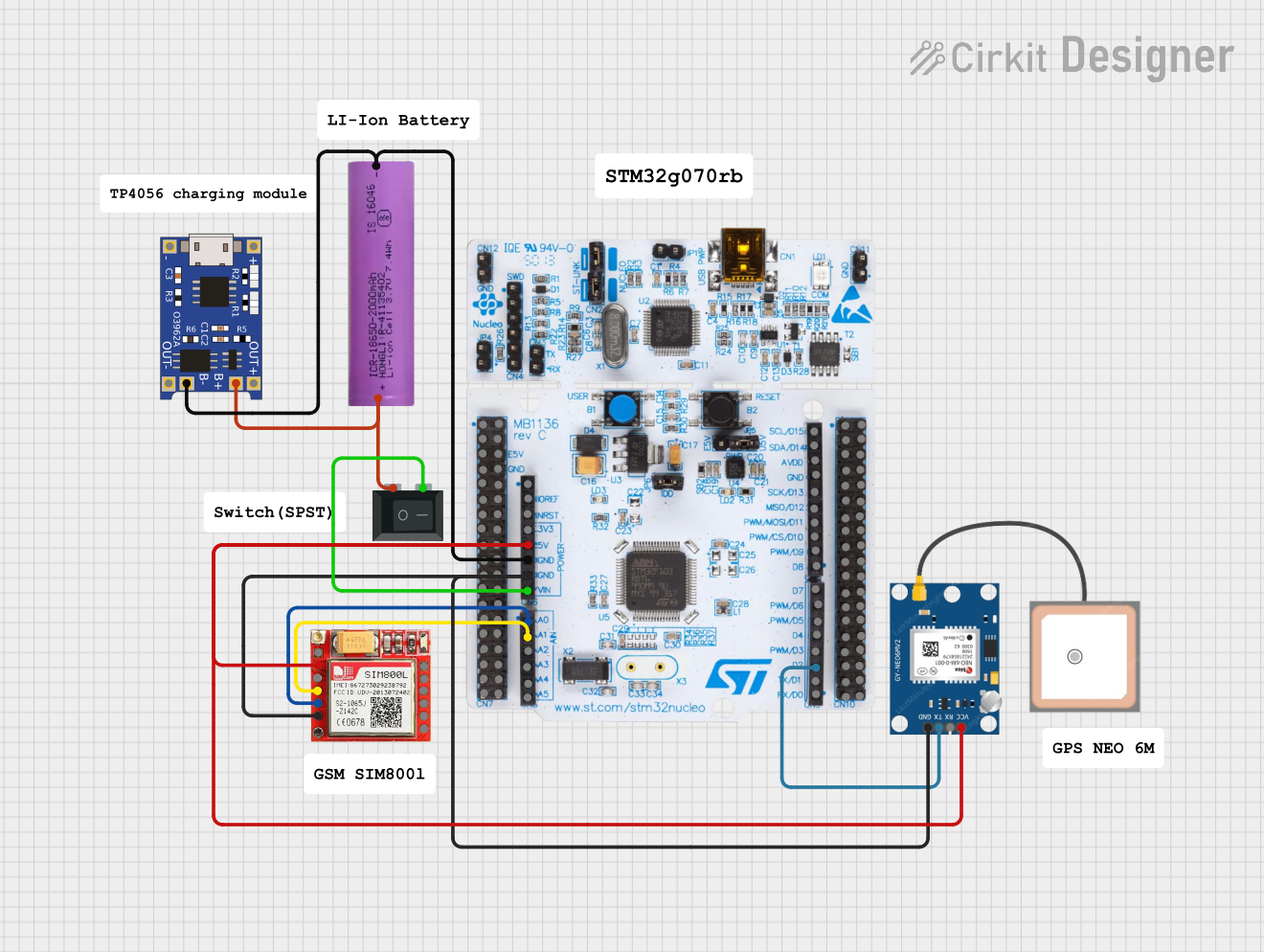
This circuit is an emergency alert system that uses a NUCLEO-F072RB microcontroller to send SMS alerts and make calls via a SIM800L GSM module, while obtaining location data from a GPS NEO 6M module. The system is powered by a Li-ion battery and includes a TP4056 module for battery charging and protection, with a rocker switch to control power to the microcontroller.
Below are the key technical details of the IRLZ44N MOSFET:
Parameter
Value
Type
N-Channel MOSFET
Maximum Drain-Source Voltage (VDS)
55V
Maximum Gate-Source Voltage (VGS)
±16V
Continuous Drain Current (ID) @ 25°C
47A
Pulsed Drain Current (IDM)
160A
On-Resistance (RDS(on)) @ VGS = 5V
22 mΩ
Gate Threshold Voltage (VGS(th))
1V to 2V
Power Dissipation (PD)
94W
Operating Temperature Range
-55°C to +175°C
Package Type
TO-220
Pin Configuration
The IRLZ44N has three pins, as shown in the table below:
Pin Number
Pin Name
Description
1
Gate (G)
Controls the MOSFET switching state.
2
Drain (D)
Current flows from drain to source when the MOSFET is on.
3
Source (S)
Connected to ground or the negative terminal of the load.
Usage Instructions
How to Use the IRLZ44N in a Circuit
Gate Control: Connect the gate pin to a microcontroller (e.g., Arduino UNO) or a logic-level signal. Use a resistor (typically 220Ω to 1kΩ) between the microcontroller pin and the gate to limit inrush current.
Drain Connection: Connect the drain pin to the positive terminal of the load (e.g., motor, LED strip).
Source Connection: Connect the source pin to ground or the negative terminal of the power supply.
Power Supply: Ensure the voltage across the drain and source does not exceed 55V, and the gate voltage does not exceed ±16V.
Important Considerations
Logic-Level Operation: The IRLZ44N is a logic-level MOSFET, meaning it can be fully turned on with a gate voltage as low as 5V, making it compatible with 5V microcontrollers like the Arduino UNO.
Heat Dissipation: For high-current applications, use a heatsink to prevent overheating.
Flyback Diode: When driving inductive loads (e.g., motors, relays), include a flyback diode across the load to protect the MOSFET from voltage spikes.
Example: Controlling a DC Motor with Arduino UNO
Below is an example circuit and code to control a DC motor using the IRLZ44N and an Arduino UNO.
Circuit Diagram
Gate: Connect to Arduino digital pin (e.g., D9) through a 220Ω resistor.
Drain: Connect to one terminal of the motor.
Source: Connect to ground.
Motor Power Supply: Connect the positive terminal to the other motor terminal and the negative terminal to ground.
Arduino Code
// Define the pin connected to the MOSFET gate
const int mosfetGatePin = 9;

void setup() {
  // Set the MOSFET gate pin as an output
  pinMode(mosfetGatePin, OUTPUT);
}

void loop() {
  // Turn the motor on by setting the gate HIGH
  digitalWrite(mosfetGatePin, HIGH);
  delay(2000); // Keep the motor on for 2 seconds

  // Turn the motor off by setting the gate LOW
  digitalWrite(mosfetGatePin, LOW);
  delay(2000); // Keep the motor off for 2 seconds
}
Best Practices
Use a pull-down resistor (10kΩ) between the gate and source to ensure the MOSFET remains off when no signal is applied.
Avoid exceeding the maximum ratings for voltage, current, and power dissipation to prevent damage.
Troubleshooting and FAQs
Common Issues
MOSFET Not Turning On:
Ensure the gate voltage is at least 5V for full conduction.
Check for a proper connection between the gate and the microcontroller.
Excessive Heat:
Verify that the current through the MOSFET does not exceed its rated limit.
Use a heatsink or active cooling for high-power applications.
Load Not Operating:
Check the connections to the load and power supply.
Ensure the MOSFET is not damaged by testing it with a multimeter.
FAQs
Q: Can the IRLZ44N be used with a 3.3V microcontroller?
A: While the IRLZ44N is a logic-level MOSFET, it may not fully turn on with a 3.3V gate signal. For optimal performance, use a MOSFET driver or a 5V logic-level signal.
Q: Do I need a heatsink for the IRLZ44N?
A: A heatsink is recommended for applications where the MOSFET handles high currents (e.g., above 10A) to prevent overheating.
Q: Can I use the IRLZ44N for AC loads?
A: No, the IRLZ44N is designed for DC applications. For AC loads, consider using a TRIAC or an IGBT.
By following this documentation, you can effectively integrate the IRLZ44N into your electronic projects and ensure reliable performance.


 Open Project in Cirkit Designer