
How to Use IRLML6402: Examples, Pinouts, and Specs
 Design with IRLML6402 in Cirkit Designer
Introduction
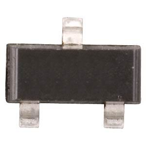
The IRLML6402 is a low-voltage N-channel MOSFET manufactured by Infineon Technologies (Part ID: IRLML6402TRPBF). This component is designed for applications requiring high efficiency, low on-resistance, and fast switching speeds. Its compact SOT-23 package makes it ideal for space-constrained designs.
Explore Projects Built with IRLML6402
 Open Project in Cirkit Designer
 Open Project in Cirkit Designer
 Open Project in Cirkit Designer
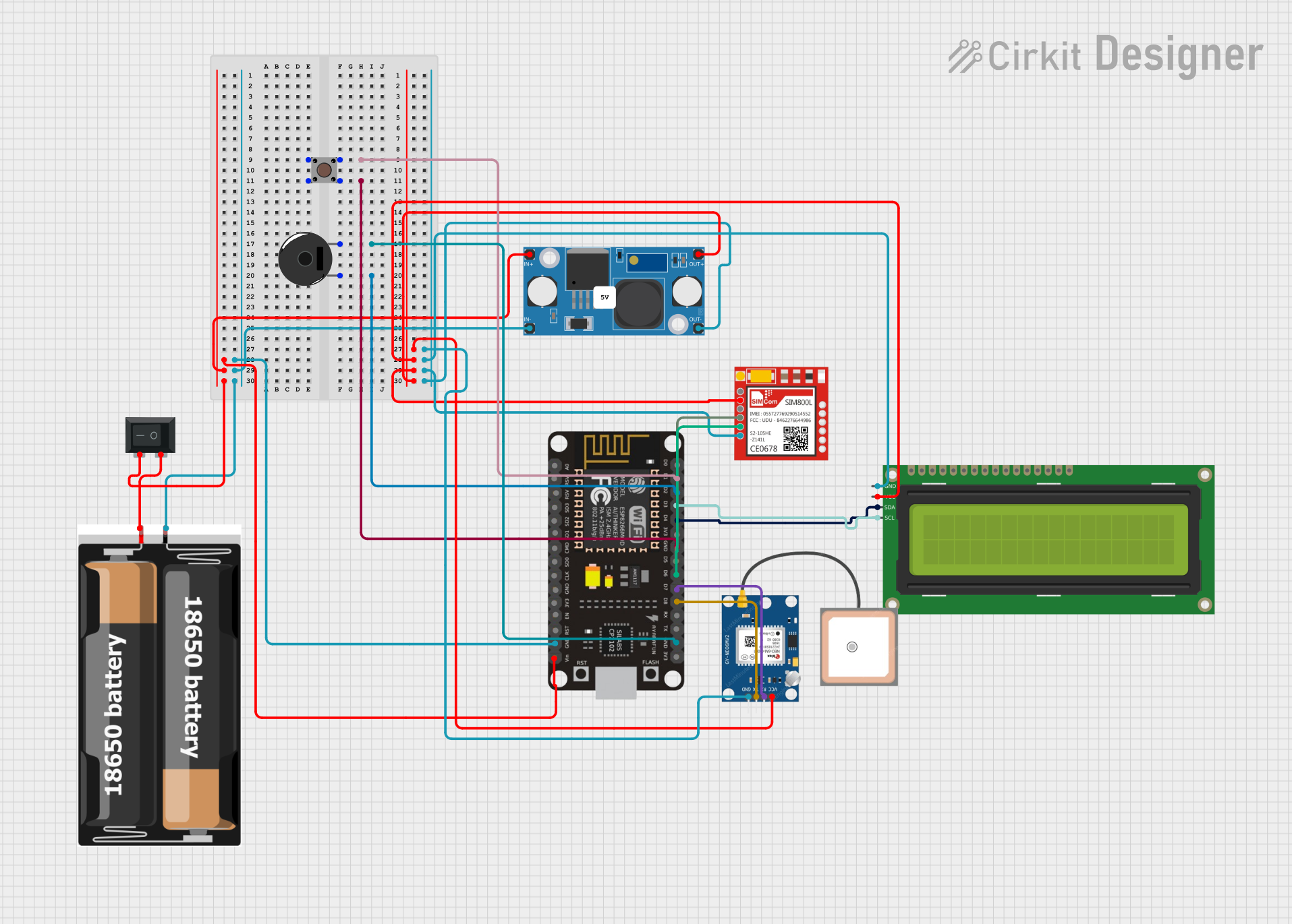
 Open Project in Cirkit Designer
Explore Projects Built with IRLML6402

 Open Project in Cirkit Designer
 Open Project in Cirkit Designer
 Open Project in Cirkit Designer
 Open Project in Cirkit Designer
Common Applications
- Power management in portable devices
- DC-DC converters
- Load switching in battery-powered systems
- Motor control circuits
- General-purpose switching applications
Technical Specifications
The following table outlines the key technical specifications of the IRLML6402:
| Parameter | Value |
|---|---|
| Drain-Source Voltage (VDS) | 20V |
| Gate-Source Voltage (VGS) | ±12V |
| Continuous Drain Current (ID) | 3.7A (at VGS = 4.5V, TA = 25°C) |
| Pulsed Drain Current (IDM) | 11A |
| On-Resistance (RDS(on)) | 0.028Ω (at VGS = 4.5V, ID = 3.7A) |
| Power Dissipation (PD) | 1.25W (TA = 25°C) |
| Operating Temperature Range | -55°C to +150°C |
| Package | SOT-23 |
Pin Configuration
The IRLML6402 is housed in a 3-pin SOT-23 package. The pinout is as follows:
| Pin Number | Pin Name | Description |
|---|---|---|
| 1 | Gate (G) | Controls the MOSFET switching |
| 2 | Source (S) | Connected to the source of current |
| 3 | Drain (D) | Connected to the load or output |
Usage Instructions
How to Use the IRLML6402 in a Circuit
- Power Supply: Ensure the drain-source voltage (VDS) does not exceed 20V and the gate-source voltage (VGS) stays within ±12V.
- Gate Drive: Use a gate drive voltage of 4.5V or higher to fully turn on the MOSFET and achieve low on-resistance.
- Load Connection: Connect the load between the drain pin and the positive supply voltage. The source pin should be connected to ground.
- Gate Resistor: Add a resistor (typically 10Ω–100Ω) in series with the gate to limit inrush current and prevent oscillations.
- Protection: Use a flyback diode across inductive loads to protect the MOSFET from voltage spikes during switching.
Example Circuit with Arduino UNO
The IRLML6402 can be used to control a small DC motor with an Arduino UNO. Below is an example circuit and code:
Circuit Description
- Connect the drain of the IRLML6402 to one terminal of the motor.
- Connect the other terminal of the motor to the positive supply (e.g., 12V).
- Connect the source of the IRLML6402 to ground.
- Connect the gate to an Arduino digital pin (e.g., D9) through a 100Ω resistor.
- Add a flyback diode (e.g., 1N4007) across the motor terminals to protect the MOSFET.
Arduino Code
// IRLML6402 MOSFET Motor Control Example
// This code demonstrates how to control a DC motor using PWM.

const int motorPin = 9; // Pin connected to the MOSFET gate

void setup() {
  pinMode(motorPin, OUTPUT); // Set motorPin as an output
}

void loop() {
  // Gradually increase motor speed
  for (int speed = 0; speed <= 255; speed++) {
    analogWrite(motorPin, speed); // Write PWM signal to the gate
    delay(10); // Small delay for smooth ramp-up
  }

  delay(1000); // Run motor at full speed for 1 second

  // Gradually decrease motor speed
  for (int speed = 255; speed >= 0; speed--) {
    analogWrite(motorPin, speed); // Write PWM signal to the gate
    delay(10); // Small delay for smooth ramp-down
  }

  delay(1000); // Pause before repeating
}
Best Practices
- Avoid exceeding the maximum voltage and current ratings to prevent damage.
- Use proper heat dissipation techniques (e.g., PCB copper planes) to manage power dissipation.
- Ensure the gate drive voltage is sufficient to fully turn on the MOSFET for efficient operation.
Troubleshooting and FAQs
Common Issues
MOSFET Overheating
- Cause: Exceeding the maximum current or insufficient heat dissipation.
- Solution: Check the load current and ensure proper cooling (e.g., heatsinks or PCB design).
MOSFET Not Switching
- Cause: Insufficient gate drive voltage.
- Solution: Verify that the gate voltage is at least 4.5V for full enhancement.
High Power Loss
- Cause: Operating the MOSFET in the linear region instead of saturation.
- Solution: Ensure the gate voltage is high enough to fully turn on the MOSFET.
Voltage Spikes
- Cause: Inductive loads causing back EMF.
- Solution: Add a flyback diode across the load to suppress voltage spikes.
FAQs
Q1: Can the IRLML6402 handle 5V logic levels?
Yes, the IRLML6402 is designed to operate with logic-level gate drive voltages as low as 4.5V.
Q2: Is the IRLML6402 suitable for high-frequency switching?
Yes, the IRLML6402 has fast switching characteristics, making it suitable for high-frequency applications.
Q3: Can I use the IRLML6402 for 24V systems?
No, the maximum drain-source voltage (VDS) is 20V. Exceeding this limit may damage the MOSFET.
Q4: What is the maximum current the IRLML6402 can handle?
The IRLML6402 can handle up to 3.7A continuously at 25°C, provided proper heat dissipation is ensured.