How to Use ESP8266 12-E: Examples, Pinouts, and Specs
Introduction
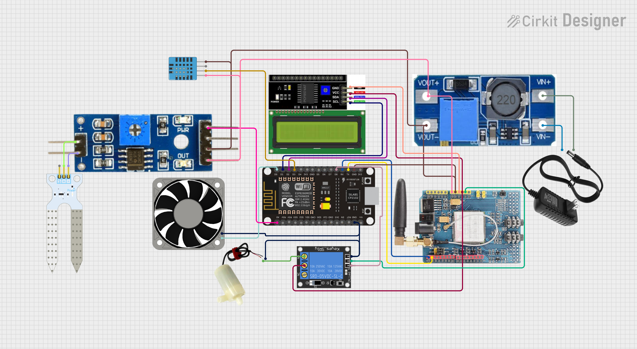
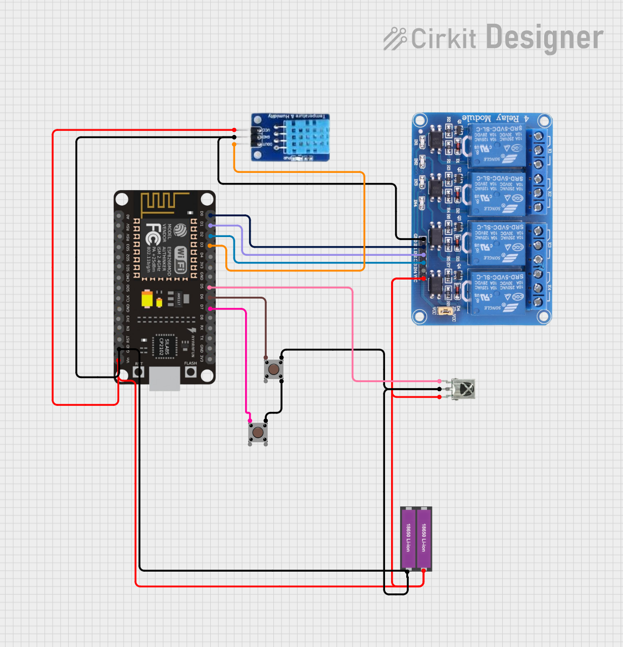
The ESP8266 12-E, manufactured by ESP8266, is a low-cost Wi-Fi microchip with an integrated full TCP/IP stack and microcontroller capability. It is widely used in Internet of Things (IoT) applications due to its affordability, compact size, and robust functionality. The module allows devices to connect to Wi-Fi networks and communicate over the internet, making it ideal for smart home devices, wireless sensors, and other IoT projects.
Explore Projects Built with ESP8266 12-E
Explore Projects Built with ESP8266 12-E
Common Applications
- Smart home automation systems
- Wireless sensor networks
- IoT-enabled devices
- Remote monitoring and control systems
- Prototyping and development of Wi-Fi-enabled projects
Technical Specifications
The ESP8266 12-E module is a powerful and versatile component. Below are its key technical details:
Key Technical Details
| Parameter | Value |
|---|---|
| Microcontroller | Tensilica L106 32-bit RISC CPU |
| Operating Voltage | 3.0V - 3.6V |
| Flash Memory | 4 MB (32 Mbit) |
| Clock Speed | 80 MHz (default), up to 160 MHz |
| Wi-Fi Standards | 802.11 b/g/n |
| Wi-Fi Security | WPA/WPA2 |
| GPIO Pins | 11 |
| Communication Protocols | UART, SPI, I2C, PWM, ADC |
| Power Consumption | 15 µA (deep sleep), ~70 mA (Wi-Fi active) |
| Operating Temperature | -40°C to 125°C |
Pin Configuration and Descriptions
The ESP8266 12-E module has 16 pins. Below is the pinout and description:
| Pin Number | Pin Name | Description |
|---|---|---|
| 1 | GND | Ground (0V reference) |
| 2 | TXD | UART Transmit (TX) for serial communication |
| 3 | RXD | UART Receive (RX) for serial communication |
| 4 | GPIO0 | General Purpose I/O, used for boot mode selection during startup |
| 5 | GPIO2 | General Purpose I/O |
| 6 | GPIO4 | General Purpose I/O |
| 7 | GPIO5 | General Purpose I/O |
| 8 | GPIO12 | General Purpose I/O |
| 9 | GPIO13 | General Purpose I/O |
| 10 | GPIO14 | General Purpose I/O |
| 11 | GPIO15 | General Purpose I/O, must be pulled LOW during boot |
| 12 | GPIO16 | General Purpose I/O, can be used for deep sleep wake-up |
| 13 | EN (CH_PD) | Chip Enable, must be HIGH for normal operation |
| 14 | VCC | Power supply input (3.3V) |
| 15 | ADC (A0) | Analog-to-Digital Converter input (0-1V range) |
| 16 | RST | Reset pin, active LOW |
Usage Instructions
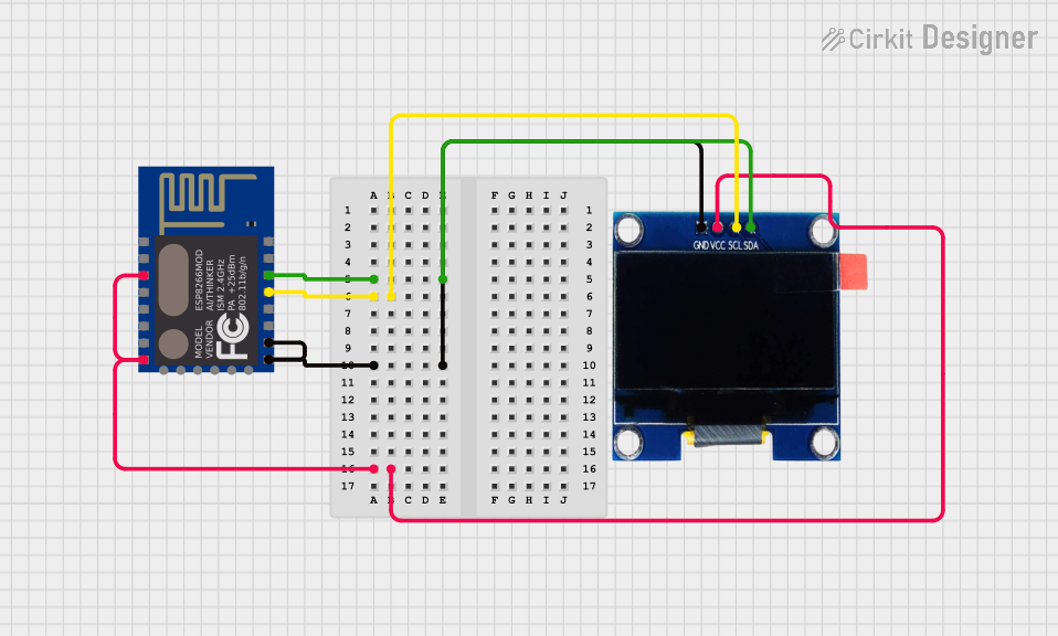
The ESP8266 12-E can be used as a standalone microcontroller or as a Wi-Fi module for other microcontrollers like the Arduino UNO. Below are the steps to use it in a circuit:
Basic Circuit Connection
- Power Supply: Connect the VCC pin to a 3.3V power source and GND to ground. Do not exceed 3.6V as it may damage the module.
- UART Communication: Connect the TXD and RXD pins to the corresponding RX and TX pins of your microcontroller (e.g., Arduino UNO). Use a logic level converter if your microcontroller operates at 5V.
- Enable Pin: Pull the EN (CH_PD) pin HIGH (connect to 3.3V) to enable the module.
- Boot Mode: Ensure GPIO0 and GPIO15 are set correctly for the desired boot mode:
- Normal operation: GPIO0 HIGH, GPIO15 LOW.
- Flashing firmware: GPIO0 LOW, GPIO15 LOW.
Example: Connecting to an Arduino UNO
Below is an example of how to connect the ESP8266 12-E to an Arduino UNO and upload a basic sketch to connect to a Wi-Fi network.
Circuit Diagram
- ESP8266 VCC → Arduino 3.3V
- ESP8266 GND → Arduino GND
- ESP8266 TXD → Arduino RX (via voltage divider for 5V to 3.3V conversion)
- ESP8266 RXD → Arduino TX
- ESP8266 EN → Arduino 3.3V
- ESP8266 GPIO0 → Arduino GND (for flashing mode)
Arduino Code Example
#include <ESP8266WiFi.h> // Include the ESP8266 Wi-Fi library

const char* ssid = "Your_SSID";       // Replace with your Wi-Fi SSID
const char* password = "Your_Password"; // Replace with your Wi-Fi password

void setup() {
  Serial.begin(115200); // Initialize serial communication
  WiFi.begin(ssid, password); // Start connecting to Wi-Fi

  Serial.print("Connecting to Wi-Fi");
  while (WiFi.status() != WL_CONNECTED) {
    delay(500);
    Serial.print("."); // Print dots while connecting
  }
  Serial.println("\nConnected to Wi-Fi!");
  Serial.print("IP Address: ");
  Serial.println(WiFi.localIP()); // Print the assigned IP address
}

void loop() {
  // Add your main code here
}
Important Considerations
- Voltage Levels: The ESP8266 operates at 3.3V. Ensure all GPIO pins and communication lines are at 3.3V logic levels.
- Power Supply: Use a stable 3.3V power source capable of supplying at least 300 mA to avoid instability.
- Firmware Updates: Update the firmware to the latest version for improved performance and bug fixes.
Troubleshooting and FAQs
Common Issues
Module Not Responding
- Cause: Incorrect wiring or insufficient power supply.
- Solution: Double-check connections and ensure a stable 3.3V power source.
Wi-Fi Connection Fails
- Cause: Incorrect SSID or password.
- Solution: Verify the credentials and ensure the Wi-Fi network is within range.
Garbage Data in Serial Monitor
- Cause: Mismatched baud rate.
- Solution: Set the Serial Monitor to the correct baud rate (e.g., 115200).
Module Overheating
- Cause: Overvoltage or excessive current draw.
- Solution: Ensure the power supply is within the specified range (3.0V - 3.6V).
FAQs
Q: Can the ESP8266 12-E be programmed directly without an external microcontroller?
A: Yes, the ESP8266 12-E has a built-in microcontroller and can be programmed using the Arduino IDE or other tools.
Q: What is the maximum range of the ESP8266 12-E Wi-Fi module?
A: The module can typically achieve a range of up to 100 meters in open space, depending on environmental factors.
Q: How do I reset the module?
A: Pull the RST pin LOW momentarily to reset the module.
Q: Can I use the ESP8266 12-E with a 5V microcontroller?
A: Yes, but you must use a logic level converter to step down the 5V signals to 3.3V for the ESP8266.