How to Use Disyuntor diferencial: Examples, Pinouts, and Specs
Introduction
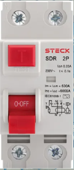
The Disyuntor Diferencial DD25A by Schneider is a differential circuit breaker designed to detect earth faults by comparing the current flowing into and out of a circuit. This device provides critical protection against electric shocks and fire hazards caused by leakage currents. It is an essential safety component in residential, commercial, and industrial electrical installations.
Explore Projects Built with Disyuntor diferencial


Explore Projects Built with Disyuntor diferencial
Common Applications and Use Cases
- Protection against electric shocks in residential and commercial buildings.
- Prevention of fire hazards caused by leakage currents.
- Ensuring compliance with electrical safety standards in industrial installations.
- Use in circuits with high sensitivity requirements, such as bathrooms, kitchens, and outdoor installations.
Technical Specifications
The following table outlines the key technical details of the DD25A:
| Parameter | Value |
|---|---|
| Manufacturer | Schneider |
| Part ID | DD25A |
| Rated Current (In) | 25 A |
| Rated Voltage (Un) | 230/400 V AC |
| Sensitivity (ΔIn) | 30 mA |
| Frequency | 50/60 Hz |
| Number of Poles | 2P (2 Poles) |
| Breaking Capacity | 6 kA |
| Operating Temperature | -25°C to +55°C |
| Mounting Type | DIN Rail |
| Standards Compliance | IEC 61008-1 |
Pin Configuration and Descriptions
The DD25A has a straightforward terminal configuration for input and output connections. The table below describes the terminals:
| Terminal | Description |
|---|---|
| L (Line In) | Connects to the live input from the power source. |
| N (Neutral In) | Connects to the neutral input from the power source. |
| L (Line Out) | Connects to the live output to the load. |
| N (Neutral Out) | Connects to the neutral output to the load. |
Usage Instructions
How to Use the DD25A in a Circuit
- Mounting: Install the DD25A on a standard DIN rail in the distribution board.
- Wiring:
- Connect the live input wire to the L (Line In) terminal.
- Connect the neutral input wire to the N (Neutral In) terminal.
- Connect the live output wire to the L (Line Out) terminal.
- Connect the neutral output wire to the N (Neutral Out) terminal.
- Testing:
- After installation, press the Test Button on the DD25A to ensure proper functionality. The breaker should trip when the button is pressed.
- Resetting:
- If the breaker trips due to a fault, identify and resolve the issue before resetting the device by flipping the switch back to the "ON" position.
Important Considerations and Best Practices
- Ensure that the total load current does not exceed the rated current of 25 A.
- Regularly test the device using the built-in test button to verify its functionality.
- Avoid using the DD25A in circuits with high transient currents, as this may cause nuisance tripping.
- Ensure proper grounding of the electrical system for optimal performance.
- Follow local electrical codes and standards during installation.
Arduino Integration
While the DD25A is not directly compatible with Arduino or other microcontrollers, it can be used in conjunction with sensors and relays to monitor and control electrical circuits. For example, you can use a current sensor with an Arduino to detect when the breaker trips and trigger an alert.
/*
  Example Arduino Code to Monitor DD25A Status
  This code uses a current sensor to detect if the breaker trips.
  When the breaker trips, the current sensor will detect no current
  flow, and the Arduino will trigger an alert (e.g., LED or buzzer).
*/

const int currentSensorPin = A0; // Analog pin connected to current sensor
const int alertPin = 13;         // Digital pin connected to an alert LED

void setup() {
  pinMode(alertPin, OUTPUT);    // Set alert pin as output
  Serial.begin(9600);           // Initialize serial communication
}

void loop() {
  int sensorValue = analogRead(currentSensorPin); // Read current sensor value
  float current = sensorValue * (5.0 / 1023.0);   // Convert to voltage (example)

  if (current < 0.1) { // If current is below threshold, breaker may be tripped
    digitalWrite(alertPin, HIGH); // Turn on alert LED
    Serial.println("Breaker tripped! Check the circuit.");
  } else {
    digitalWrite(alertPin, LOW);  // Turn off alert LED
    Serial.println("Breaker is functioning normally.");
  }

  delay(1000); // Wait 1 second before next reading
}
Troubleshooting and FAQs
Common Issues Users Might Face
Breaker Trips Frequently:
- Cause: Overload or leakage current exceeding 30 mA.
- Solution: Reduce the load on the circuit or check for faulty appliances causing leakage.
Breaker Does Not Trip During Test:
- Cause: Faulty test mechanism or improper wiring.
- Solution: Verify wiring connections and replace the breaker if necessary.
Nuisance Tripping:
- Cause: High transient currents or electromagnetic interference.
- Solution: Use a breaker with higher immunity to transients or install surge protection devices.
Breaker Does Not Reset:
- Cause: Persistent fault in the circuit.
- Solution: Inspect the circuit for faults and resolve them before resetting.
FAQs
Q1: Can the DD25A be used in a three-phase system?
A1: The DD25A is designed for single-phase systems. For three-phase systems, use a compatible three-phase differential breaker.
Q2: How often should the test button be used?
A2: It is recommended to test the breaker at least once a month to ensure proper functionality.
Q3: What happens if the load exceeds 25 A?
A3: The breaker may trip to protect the circuit. Ensure the load does not exceed the rated current.
Q4: Can the DD25A protect against short circuits?
A4: No, the DD25A is designed to detect earth leakage currents. Use it in conjunction with a circuit breaker for short-circuit protection.