How to Use E32-900M20S: Examples, Pinouts, and Specs
Introduction
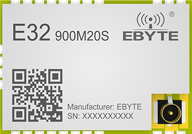
The E32-900M20S is a wireless serial communication module manufactured by CDEBYTE. It operates in the 900 MHz frequency band and is designed for long-range, low-power data transmission. This module is ideal for Internet of Things (IoT) applications, enabling devices to communicate wirelessly over distances of up to several kilometers in open environments. Its compact design and robust performance make it suitable for industrial automation, smart agriculture, remote monitoring, and other wireless communication systems.
Explore Projects Built with E32-900M20S
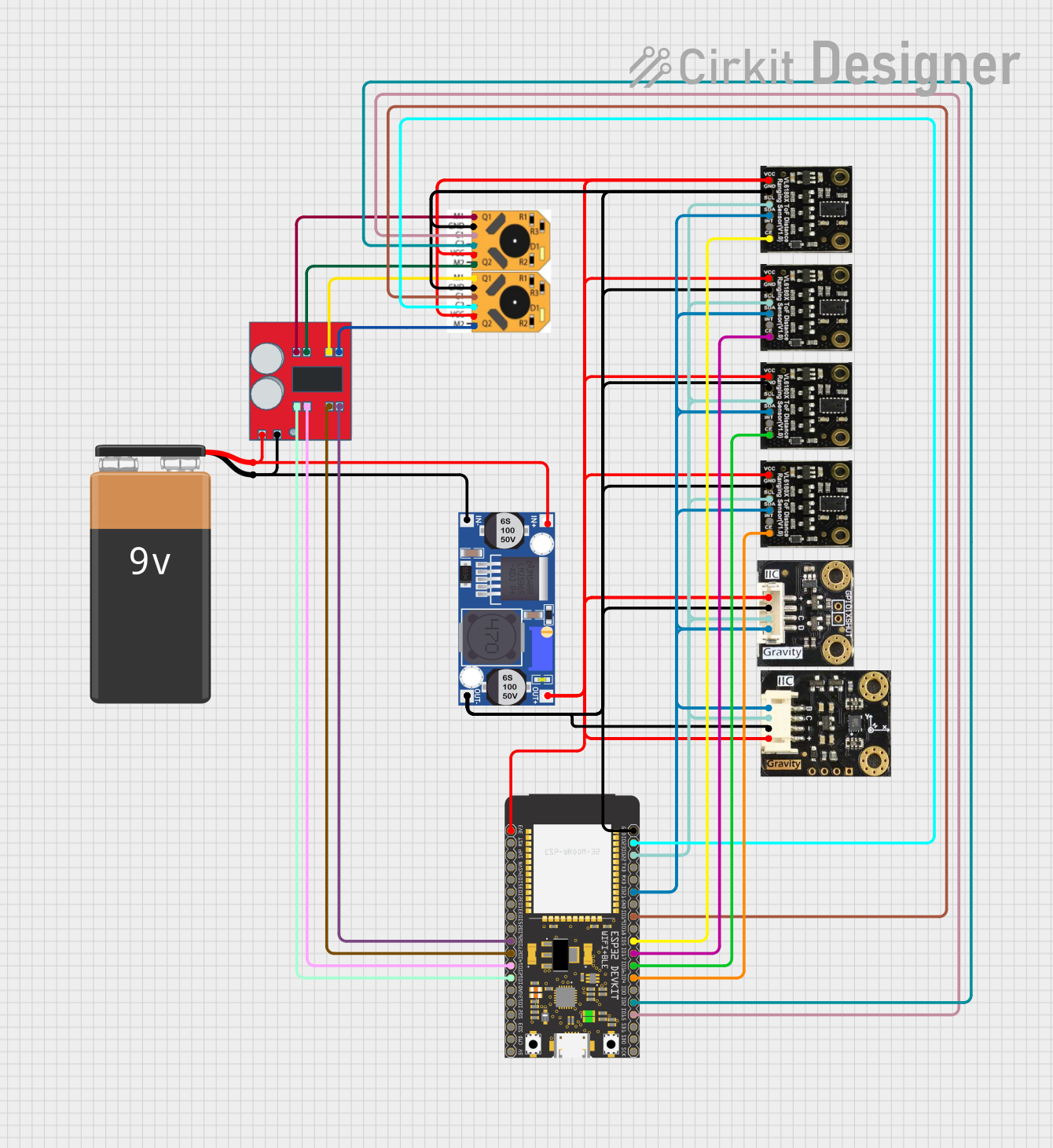


Explore Projects Built with E32-900M20S
Common Applications
- IoT Networks: Facilitates communication between IoT devices in smart homes, cities, and industries.
- Remote Monitoring: Used in systems like weather stations, water level monitoring, and energy meters.
- Smart Agriculture: Enables wireless control and monitoring of irrigation systems, soil sensors, and livestock tracking.
- Industrial Automation: Provides reliable communication in factory automation and process control systems.
Technical Specifications
Key Technical Details
| Parameter | Value |
|---|---|
| Operating Frequency | 900 MHz (902–928 MHz ISM band) |
| Communication Protocol | UART (Transparent Transmission) |
| Modulation Method | LoRa (Long Range) |
| Transmission Power | 20 dBm (100 mW) |
| Sensitivity | -138 dBm |
| Data Rate | 0.3 kbps to 19.2 kbps |
| Operating Voltage | 2.3V to 5.5V |
| Current Consumption | 100 mA (transmitting), 16 mA (receiving), <5 µA (standby mode) |
| Communication Range | Up to 5 km (line of sight, depending on environment and antenna quality) |
| Operating Temperature | -40°C to +85°C |
| Dimensions | 24 mm × 43 mm × 8 mm |
Pin Configuration and Descriptions
The E32-900M20S module has a total of 8 pins. Below is the pinout and description:
| Pin Number | Pin Name | Description |
|---|---|---|
| 1 | M0 | Mode selection pin (works with M1 to set the module's operating mode) |
| 2 | M1 | Mode selection pin (works with M0 to set the module's operating mode) |
| 3 | RXD | UART data input (connect to the TX pin of the microcontroller) |
| 4 | TXD | UART data output (connect to the RX pin of the microcontroller) |
| 5 | AUX | Status indicator pin (used for monitoring module operation) |
| 6 | VCC | Power supply input (2.3V to 5.5V) |
| 7 | GND | Ground |
| 8 | ANT | Antenna interface (connect to an external 50Ω antenna for optimal performance) |
Usage Instructions
How to Use the E32-900M20S in a Circuit
- Power Supply: Connect the VCC pin to a regulated power source (2.3V to 5.5V) and the GND pin to ground.
- UART Communication: Connect the RXD and TXD pins to the corresponding TX and RX pins of a microcontroller (e.g., Arduino UNO).
- Mode Selection: Use the M0 and M1 pins to configure the module's operating mode:
- Normal Mode: M0 = 0, M1 = 0 (for transparent data transmission)
- Wake-Up Mode: M0 = 1, M1 = 0 (for low-latency communication)
- Power-Saving Mode: M0 = 0, M1 = 1 (for low power consumption)
- Configuration Mode: M0 = 1, M1 = 1 (for setting parameters via AT commands)
- Antenna Connection: Attach a 50Ω antenna to the ANT pin for optimal signal transmission and reception.
- Status Monitoring: Use the AUX pin to monitor the module's status (e.g., busy, idle, or transmitting).
Example: Connecting to an Arduino UNO
Below is an example of how to connect the E32-900M20S to an Arduino UNO and send data wirelessly.
Wiring Diagram
| E32-900M20S Pin | Arduino UNO Pin |
|---|---|
| VCC | 5V |
| GND | GND |
| RXD | D3 (via voltage divider if using 5V logic) |
| TXD | D2 |
| M0 | D4 |
| M1 | D5 |
| AUX | D6 |
Arduino Code Example
#include <SoftwareSerial.h>

// Define pins for SoftwareSerial
SoftwareSerial E32Serial(2, 3); // RX = 2, TX = 3

// Define mode control pins
const int M0 = 4;
const int M1 = 5;
const int AUX = 6;

void setup() {
  // Initialize serial communication
  Serial.begin(9600); // For debugging
  E32Serial.begin(9600); // For E32 module communication

  // Set mode control pins as outputs
  pinMode(M0, OUTPUT);
  pinMode(M1, OUTPUT);
  pinMode(AUX, INPUT);

  // Set module to Normal Mode (M0 = 0, M1 = 0)
  digitalWrite(M0, LOW);
  digitalWrite(M1, LOW);

  Serial.println("E32-900M20S Initialized. Ready to send data.");
}

void loop() {
  // Check if data is available from the serial monitor
  if (Serial.available()) {
    String data = Serial.readString();
    E32Serial.println(data); // Send data to E32 module
    Serial.println("Data sent: " + data);
  }

  // Check if data is received from the E32 module
  if (E32Serial.available()) {
    String receivedData = E32Serial.readString();
    Serial.println("Data received: " + receivedData);
  }
}
Important Considerations
- Voltage Levels: The RXD pin is not 5V-tolerant. Use a voltage divider or level shifter if connecting to a 5V microcontroller.
- Antenna Placement: Ensure the antenna is placed away from metal objects and other sources of interference for optimal performance.
- Mode Switching: Allow a short delay (e.g., 2 ms) after changing the M0 and M1 pin states to ensure the module transitions to the desired mode.
Troubleshooting and FAQs
Common Issues and Solutions
No Data Transmission
- Cause: Incorrect wiring or mismatched baud rates.
- Solution: Double-check the connections and ensure the baud rate of the microcontroller matches the module's default (9600 bps).
Short Communication Range
- Cause: Poor antenna placement or low transmission power.
- Solution: Use a high-quality 50Ω antenna and ensure it is placed in an open area, away from obstructions.
Module Not Responding
- Cause: Incorrect mode configuration or insufficient power supply.
- Solution: Verify the M0 and M1 pin states and ensure the power supply voltage is within the specified range.
Data Corruption
- Cause: Interference or mismatched data formats.
- Solution: Use a lower data rate for better reliability and ensure both devices use the same UART settings.
FAQs
Q: Can the E32-900M20S communicate with other LoRa modules?
A: Yes, as long as the frequency, data rate, and other parameters are configured to match.Q: What is the maximum range of the module?
A: Up to 5 km in line-of-sight conditions, depending on the environment and antenna quality.Q: How do I configure the module parameters?
A: Set the module to Configuration Mode (M0 = 1, M1 = 1) and use AT commands via UART.
This concludes the documentation for the E32-900M20S. For further details, refer to the official datasheet provided by CDEBYTE.