How to Use Boost Converter: Examples, Pinouts, and Specs
Introduction
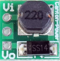
A Boost Converter is a type of DC-DC converter that steps up (increases) the input voltage to a higher output voltage while maintaining power balance. It achieves this through the use of an inductor, switch (typically a transistor), diode, and capacitor. The boost converter is widely used in applications where a higher voltage is required from a lower voltage source, such as in battery-powered devices, renewable energy systems, and automotive electronics.
Explore Projects Built with Boost Converter
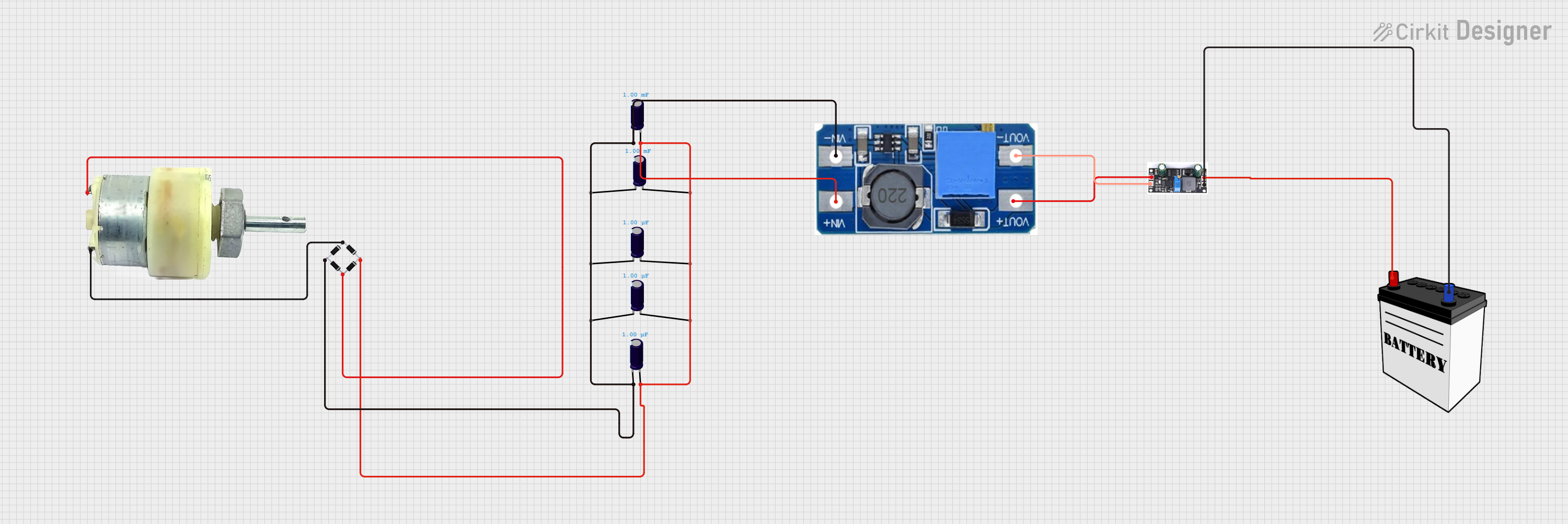


Explore Projects Built with Boost Converter
Common Applications and Use Cases
- Powering high-voltage devices from low-voltage batteries
- Solar power systems to step up panel voltage
- LED drivers for high-power LEDs
- Electric vehicles and hybrid systems
- Portable electronics requiring efficient voltage conversion
Technical Specifications
Below are the general technical specifications for a typical boost converter module. Note that specific values may vary depending on the exact model or design.
Key Technical Details
- Input Voltage Range: 3V to 32V DC
- Output Voltage Range: 5V to 35V DC (adjustable)
- Maximum Output Current: 2A (varies by model)
- Efficiency: Up to 95% (depending on load and input/output voltage)
- Switching Frequency: 150 kHz (typical)
- Operating Temperature: -40°C to +85°C
Pin Configuration and Descriptions
The following table describes the pinout for a common boost converter module:
| Pin Name | Description |
|---|---|
| VIN | Positive input voltage terminal (connect to the DC power source). |
| GND | Ground terminal (common ground for input and output). |
| VOUT | Positive output voltage terminal (provides the boosted voltage). |
| ADJ (optional) | Adjustment pin for setting the output voltage (via a potentiometer or resistor). |
Usage Instructions
How to Use the Boost Converter in a Circuit
- Connect the Input Voltage:
- Connect the positive terminal of your DC power source to the
VINpin. - Connect the negative terminal of your power source to the
GNDpin.
- Connect the positive terminal of your DC power source to the
- Connect the Load:
- Connect the positive terminal of your load to the
VOUTpin. - Connect the negative terminal of your load to the
GNDpin.
- Connect the positive terminal of your load to the
- Adjust the Output Voltage (if applicable):
- Use the onboard potentiometer (or external resistor) to set the desired output voltage.
- Measure the output voltage using a multimeter while adjusting.
- Power On:
- Turn on the input power source and verify the output voltage.
Important Considerations and Best Practices
- Input Voltage Range: Ensure the input voltage is within the specified range of the boost converter module.
- Output Voltage Adjustment: Do not exceed the maximum output voltage rating to avoid damaging the module or connected devices.
- Heat Dissipation: For high current loads, ensure proper heat dissipation using heatsinks or active cooling.
- Capacitor Selection: Use low-ESR capacitors for input and output filtering to reduce voltage ripple.
- Load Requirements: Ensure the load does not draw more current than the maximum output current rating.
Example: Using a Boost Converter with Arduino UNO
Below is an example of using a boost converter to power a 12V device from a 5V Arduino UNO power source.
Circuit Connections
- Connect the Arduino's 5V pin to the
VINpin of the boost converter. - Connect the Arduino's GND pin to the
GNDpin of the boost converter. - Connect the
VOUTpin of the boost converter to the positive terminal of the 12V device. - Connect the negative terminal of the 12V device to the
GNDpin of the boost converter.
Arduino Code Example
// Example code to control a 12V device powered by a boost converter
// The Arduino sends a PWM signal to control the device's brightness or speed.

const int pwmPin = 9; // PWM pin connected to the device

void setup() {
  pinMode(pwmPin, OUTPUT); // Set the PWM pin as an output
}

void loop() {
  // Gradually increase the PWM signal from 0 to 255
  for (int dutyCycle = 0; dutyCycle <= 255; dutyCycle++) {
    analogWrite(pwmPin, dutyCycle); // Write PWM signal to the pin
    delay(10); // Small delay for smooth transition
  }

  // Gradually decrease the PWM signal from 255 to 0
  for (int dutyCycle = 255; dutyCycle >= 0; dutyCycle--) {
    analogWrite(pwmPin, dutyCycle); // Write PWM signal to the pin
    delay(10); // Small delay for smooth transition
  }
}
Troubleshooting and FAQs
Common Issues and Solutions
No Output Voltage:
- Cause: Input voltage is not connected or is below the minimum required.
- Solution: Verify the input voltage and connections. Ensure it is within the specified range.
Output Voltage is Incorrect:
- Cause: Output voltage is not properly adjusted.
- Solution: Use a multimeter to measure and adjust the output voltage using the potentiometer.
Excessive Heat:
- Cause: High current load or insufficient cooling.
- Solution: Reduce the load current or add a heatsink to the module.
Voltage Ripple or Noise:
- Cause: Insufficient filtering or poor-quality capacitors.
- Solution: Add low-ESR capacitors to the input and output terminals.
FAQs
Q: Can I use a boost converter to power a 12V motor from a 5V battery?
- A: Yes, as long as the motor's current draw does not exceed the boost converter's maximum output current rating.
Q: What happens if I exceed the input voltage range?
- A: Exceeding the input voltage range can damage the boost converter. Always stay within the specified range.
Q: Can I use the boost converter with an Arduino UNO?
- A: Yes, you can use the boost converter to step up the Arduino's 5V output to a higher voltage for powering external devices.
Q: How do I reduce voltage ripple?
- A: Use low-ESR capacitors on the input and output, and ensure proper grounding in your circuit.
This concludes the documentation for the Boost Converter.