Cirkit Designer LogoCirkit DesignerYour all-in-one circuit design IDE Launch Cirkit Designer App

How to Use sim800c development board: Examples, Pinouts, and Specs

Image of sim800c development boardDesign with sim800c development board in Cirkit Designer

Introduction

The SIM800C Development Board is a compact GSM/GPRS module designed for mobile communication. It enables functionalities such as SMS, voice calls, and data transmission over cellular networks. This module is widely used in IoT applications, remote monitoring systems, and embedded projects requiring cellular connectivity. Its small size, low power consumption, and versatile features make it an excellent choice for developers and hobbyists alike.

Explore Projects Built with sim800c development board

Use Cirkit Designer to design, explore, and prototype these projects online. Some projects support real-time simulation. Click "Open Project" to start designing instantly!
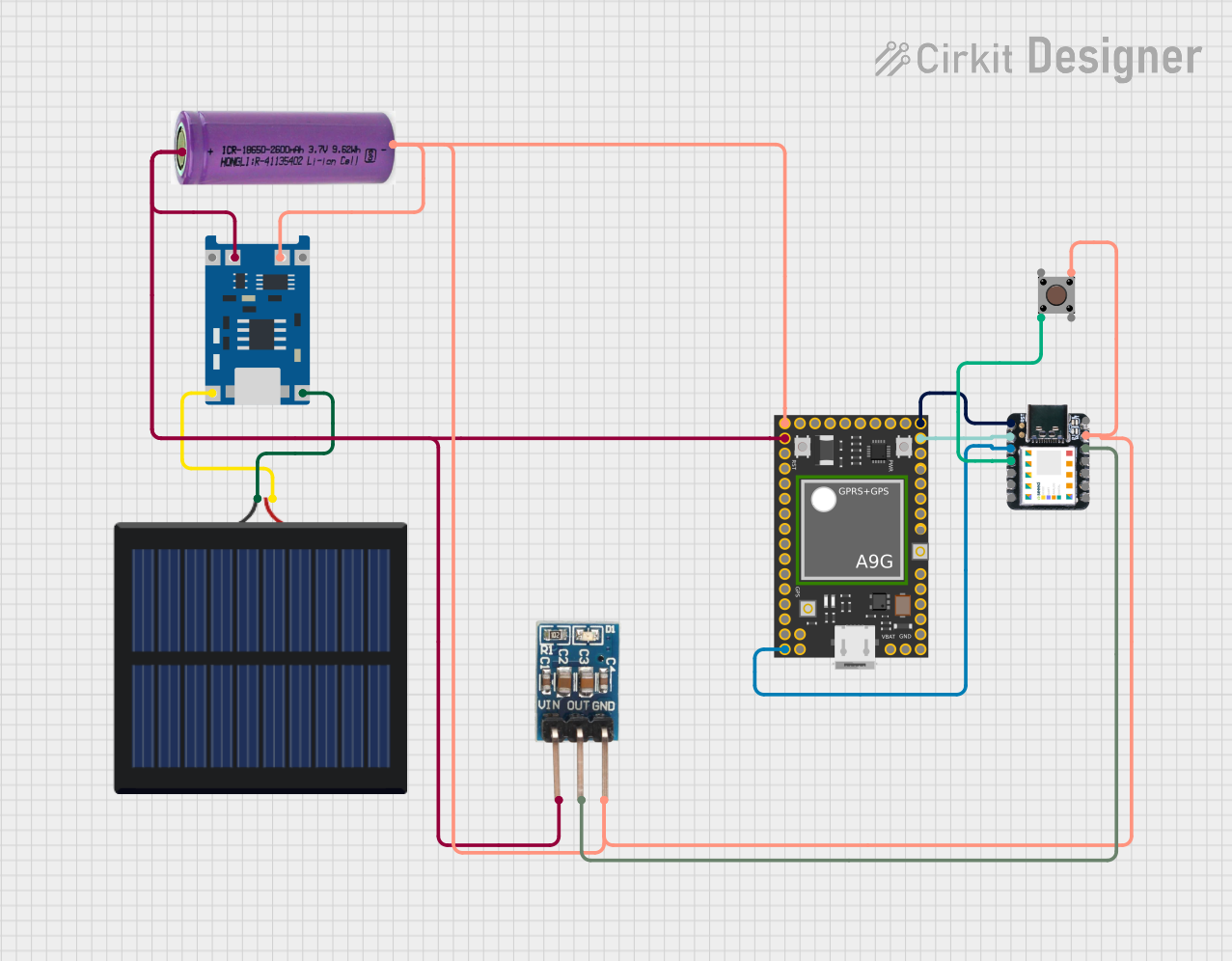
Image of Solar-Powered GSM/GPRS+GPS Tracker with Seeeduino XIAO: A project utilizing sim800c development board in a practical application

Solar-Powered GSM/GPRS+GPS Tracker with Seeeduino XIAO

This circuit features an Ai Thinker A9G development board for GSM/GPRS and GPS/BDS connectivity, interfaced with a Seeeduino XIAO microcontroller for control and data processing. A solar cell, coupled with a TP4056 charging module, charges a 3.3V battery, which powers the system through a 3.3V regulator ensuring stable operation. The circuit likely serves for remote data communication and location tracking, with the capability to be powered by renewable energy and interfaced with additional sensors or input devices via the Seeeduino XIAO.

Open Project in Cirkit Designer
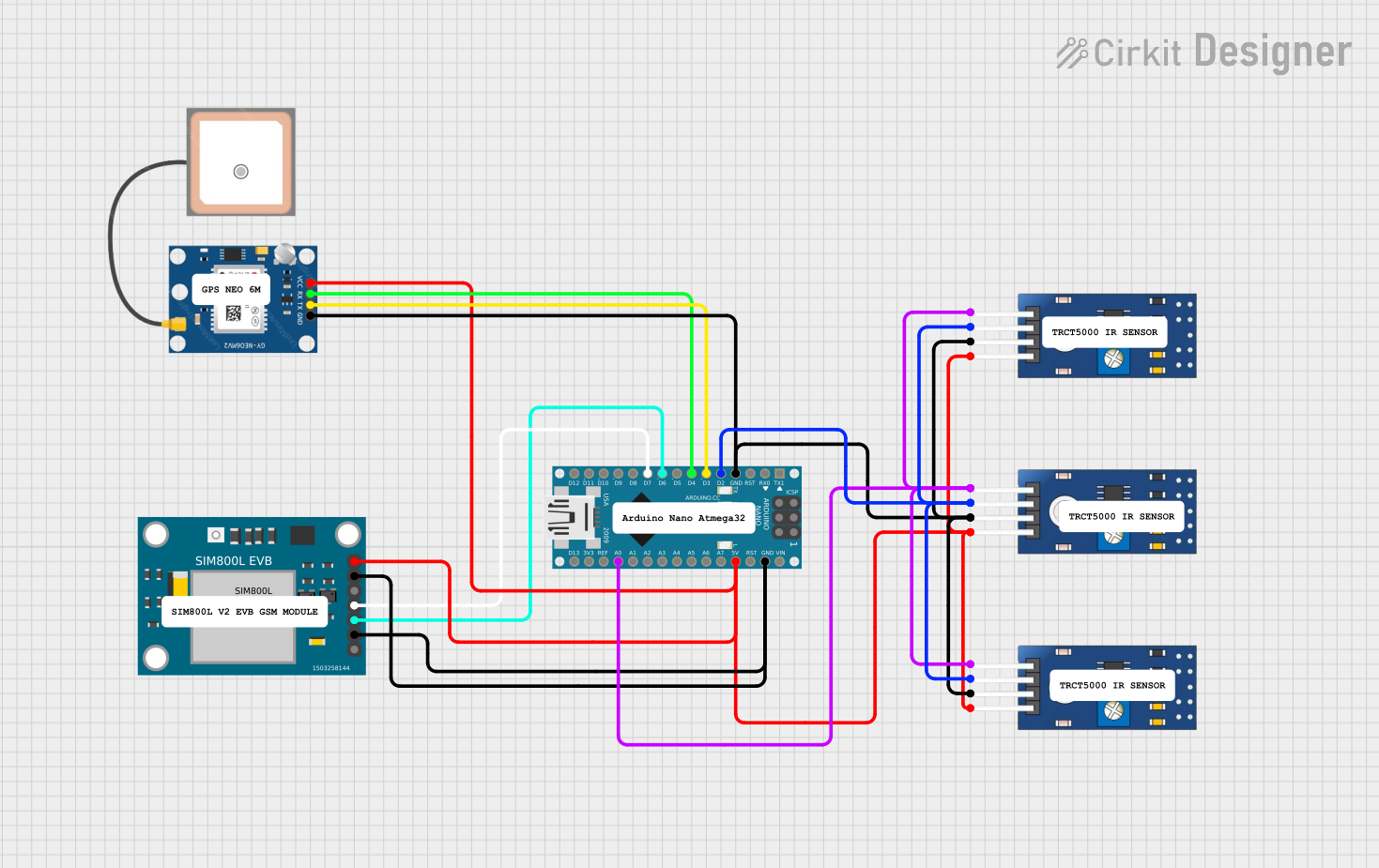
Image of Arduino Nano-Based GPS Tracker with GSM Communication and IR Obstacle Detection: A project utilizing sim800c development board in a practical application
Arduino Nano-Based GPS Tracker with GSM Communication and IR Obstacle Detection

This circuit features an Arduino Nano interfaced with a SIM800L EVB GSM module for cellular communication, a GPS NEO 6M module for location tracking, and three TCRT 5000 IR sensors for object detection or line tracking. The Arduino facilitates data exchange between the GPS and GSM modules and processes signals from the IR sensors. The provided code skeleton suggests that the Arduino is programmed to perform tasks in a loop, but specific functionality is not detailed in the code.

Open Project in Cirkit Designer
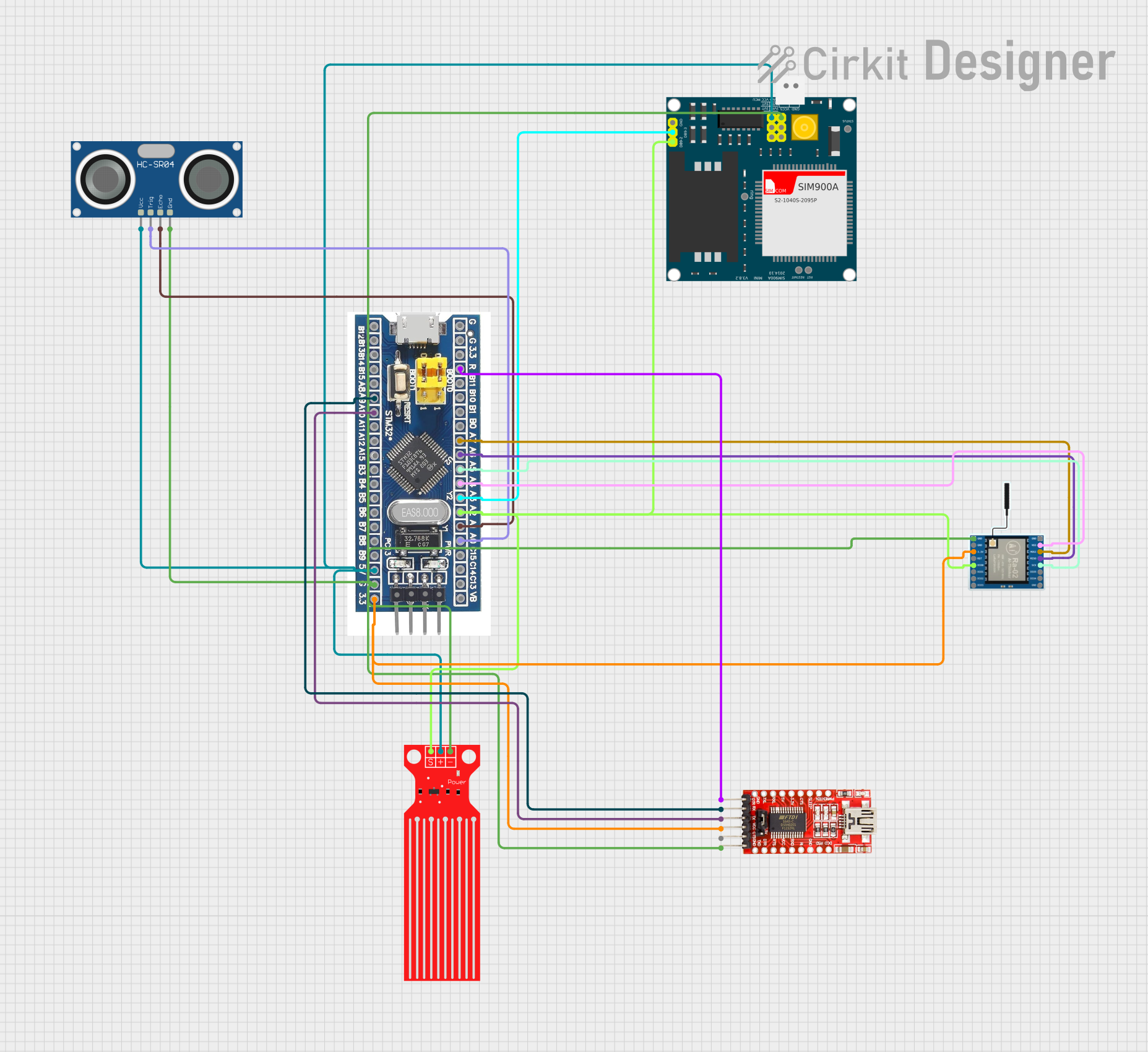
Image of STM32F103C8T6-Based Water Level Monitoring and Communication System with SIM900A and LoRa Connectivity: A project utilizing sim800c development board in a practical application
STM32F103C8T6-Based Water Level Monitoring and Communication System with SIM900A and LoRa Connectivity

This circuit features a microcontroller (STM32F103C8T6) interfaced with a SIM900A GSM module, an HC-SR04 ultrasonic sensor, a water level sensor, and a LoRa Ra-02 SX1278 module for long-range communication. The STM32F103C8T6 is configured to communicate with the GSM module and LoRa module via serial connections, and it reads data from the ultrasonic and water level sensors. An FTDI Programmer is connected for programming and serial communication with the microcontroller.

Open Project in Cirkit Designer

Common Applications and Use Cases

Technical Specifications

The SIM800C Development Board is built around the SIM800C GSM/GPRS module, offering robust communication capabilities. Below are its key technical details:

Key Technical Details

Pin Configuration and Descriptions

The SIM800C Development Board typically includes the following pins for interfacing:

Pin Name Description Direction
VCC Power supply input (3.4V to 4.4V) Input
GND Ground -
TXD UART Transmit (data from SIM800C) Output
RXD UART Receive (data to SIM800C) Input
RST Reset pin (active low) Input
NET Network status indicator (blinking LED) Output
DTR Data Terminal Ready (for sleep mode) Input
MIC+ Microphone positive input Input
MIC- Microphone negative input Input
SPK+ Speaker positive output Output
SPK- Speaker negative output Output

Usage Instructions

How to Use the SIM800C Development Board in a Circuit

  1. Power Supply: Ensure a stable power supply of 4.0V (nominal). Use a capacitor (e.g., 1000µF) near the VCC and GND pins to handle peak current demands during GSM transmission.
  2. UART Communication: Connect the TXD and RXD pins to the UART pins of your microcontroller (e.g., Arduino UNO). Use a level shifter if your microcontroller operates at 5V logic levels.
  3. SIM Card: Insert a valid SIM card into the SIM card slot. Ensure the SIM card is activated and has sufficient balance for SMS, calls, or data usage.
  4. Antenna: Attach a GSM antenna to the module for reliable network connectivity.
  5. Initialization: Use AT commands to configure the module. For example, send AT to check communication and AT+CSQ to check signal strength.

Important Considerations and Best Practices

Example: Connecting to an Arduino UNO

Below is an example of how to send an SMS using the SIM800C Development Board and an Arduino UNO:

Circuit Connections

Arduino Code

#include <SoftwareSerial.h>

// Define RX and TX pins for SoftwareSerial
SoftwareSerial sim800c(10, 11); // RX = Pin 10, TX = Pin 11

void setup() {
  // Initialize serial communication with SIM800C
  sim800c.begin(9600);
  Serial.begin(9600);

  // Wait for the module to initialize
  delay(1000);
  Serial.println("Initializing SIM800C...");

  // Send AT command to check communication
  sim800c.println("AT");
  delay(1000);
  while (sim800c.available()) {
    Serial.write(sim800c.read());
  }

  // Send SMS command
  sim800c.println("AT+CMGF=1"); // Set SMS mode to text
  delay(1000);
  sim800c.println("AT+CMGS=\"+1234567890\""); // Replace with recipient's number
  delay(1000);
  sim800c.println("Hello, this is a test SMS from SIM800C!"); // SMS content
  delay(1000);
  sim800c.write(26); // Send Ctrl+Z to send the SMS
  delay(5000);

  Serial.println("SMS sent!");
}

void loop() {
  // No actions in loop
}

Troubleshooting and FAQs

Common Issues and Solutions

  1. Module Not Responding to AT Commands:

    • Ensure the power supply is stable and within the required voltage range.
    • Check the UART connections (TXD and RXD) and ensure they are not swapped.
    • Verify the baud rate (default: 9600 bps).
  2. No Network Connectivity:

    • Check the SIM card for proper insertion and activation.
    • Ensure the antenna is securely connected and placed in an area with good signal strength.
    • Use the AT+CSQ command to check signal quality (values above 10 are acceptable).
  3. Module Restarts During Operation:

    • This is often caused by insufficient power supply. Use a capacitor (e.g., 1000µF) near the VCC pin to handle peak current demands.
  4. SMS Not Sending:

    • Ensure the SIM card has sufficient balance.
    • Verify the recipient's phone number format (e.g., include the country code).

FAQs