How to Use RJ45 Ethernet: Examples, Pinouts, and Specs
Introduction
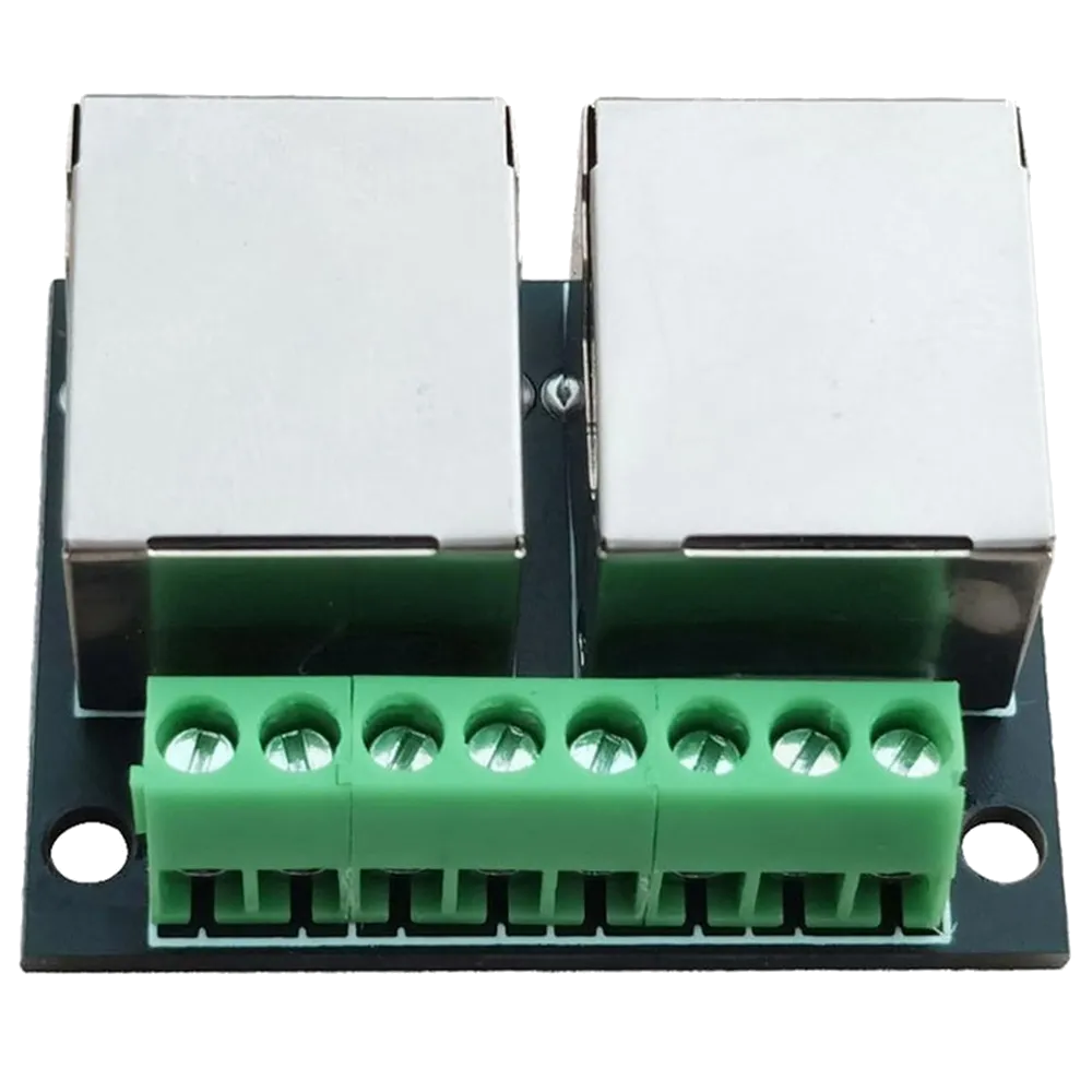
The RJ45 Ethernet connector is a standardized interface widely used for Ethernet networking. It features eight pins and is commonly employed to connect computers, routers, switches, and other devices to local area networks (LANs). Its compact design and reliable performance make it a staple in both residential and commercial networking setups.
Explore Projects Built with RJ45 Ethernet
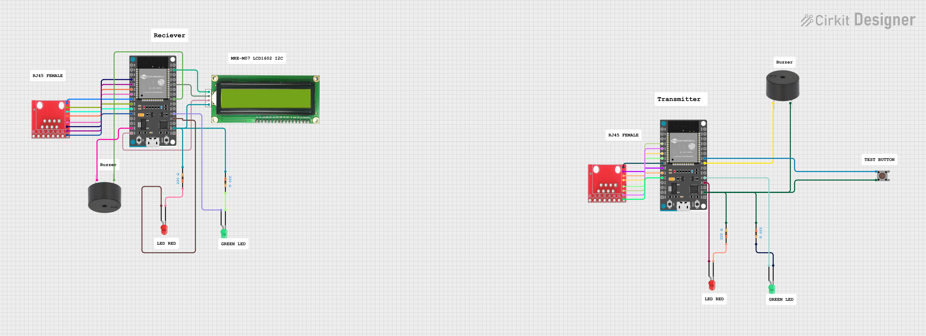
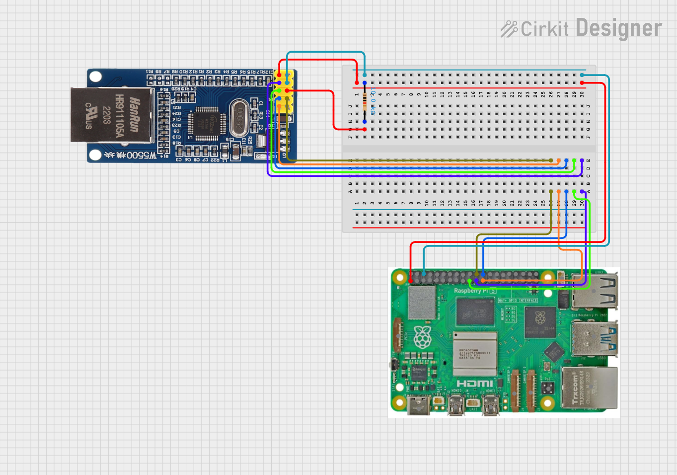


Explore Projects Built with RJ45 Ethernet
Common Applications and Use Cases
- Connecting computers, routers, and switches in LANs
- Establishing wired internet connections
- Industrial and commercial networking systems
- Power over Ethernet (PoE) applications
- Data transfer in structured cabling systems
Technical Specifications
The RJ45 Ethernet connector is designed to meet the requirements of Ethernet standards, including 10BASE-T, 100BASE-TX, and 1000BASE-T (Gigabit Ethernet). Below are its key technical details:
Key Technical Details
- Connector Type: RJ45 (8P8C - 8 positions, 8 contacts)
- Supported Standards: IEEE 802.3 (Ethernet), IEEE 802.3af/at (PoE)
- Maximum Data Rate: Up to 1 Gbps (Gigabit Ethernet)
- Voltage Rating: 125V AC/DC (typical)
- Current Rating: 1.5A per contact (maximum)
- Operating Temperature: -40°C to +85°C
- Contact Material: Gold-plated contacts for corrosion resistance
- Cable Compatibility: Cat5, Cat5e, Cat6, Cat6a, and higher
Pin Configuration and Descriptions
The RJ45 connector features eight pins, each with a specific function depending on the Ethernet standard being used. Below is the pinout for T568B wiring, which is the most commonly used standard:
| Pin Number | Wire Color (T568B) | Function |
|---|---|---|
| 1 | Orange/White | Transmit Data + (TX+) |
| 2 | Orange | Transmit Data - (TX-) |
| 3 | Green/White | Receive Data + (RX+) |
| 4 | Blue | Unused (or PoE Positive) |
| 5 | Blue/White | Unused (or PoE Positive) |
| 6 | Green | Receive Data - (RX-) |
| 7 | Brown/White | Unused (or PoE Negative) |
| 8 | Brown | Unused (or PoE Negative) |
Note: The T568A wiring standard uses a different color scheme but serves the same functional purpose.
Usage Instructions
How to Use the RJ45 Ethernet Connector in a Circuit
Prepare the Ethernet Cable:
- Use a Cat5e or higher Ethernet cable for optimal performance.
- Strip approximately 1 inch of the cable jacket to expose the twisted pairs.
- Untwist the pairs and arrange the wires according to the T568B or T568A standard.
Crimp the Connector:
- Insert the wires into the RJ45 connector, ensuring they align with the correct pinout.
- Use an RJ45 crimping tool to secure the connector to the cable.
Connect to Devices:
- Plug the RJ45 connector into the Ethernet port of your device (e.g., computer, router, or switch).
- Ensure a snug fit for reliable connectivity.
Test the Connection:
- Use a network cable tester to verify the wiring and connectivity.
- Check for proper data transmission and network functionality.
Important Considerations and Best Practices
- Always use high-quality cables and connectors to minimize signal loss and interference.
- Follow the T568B or T568A wiring standard consistently to avoid mismatched connections.
- For Power over Ethernet (PoE) applications, ensure the connector and cable are rated for the required power levels.
- Avoid bending or kinking the cable to maintain signal integrity.
Example: Connecting an RJ45 Ethernet Cable to an Arduino UNO
The Arduino UNO can be connected to an Ethernet network using an Ethernet shield. Below is an example code snippet for using the Ethernet library to establish a basic connection:
#include <SPI.h>
#include <Ethernet.h>

// MAC address for the Ethernet shield
byte mac[] = { 0xDE, 0xAD, 0xBE, 0xEF, 0xFE, 0xED };

// IP address for the Arduino (adjust as needed)
IPAddress ip(192, 168, 1, 177);

// Initialize the Ethernet server on port 80
EthernetServer server(80);

void setup() {
  // Start the Ethernet connection
  Ethernet.begin(mac, ip);

  // Start the server
  server.begin();

  // Print the IP address to the Serial Monitor
  Serial.begin(9600);
  Serial.print("Server is at ");
  Serial.println(Ethernet.localIP());
}

void loop() {
  // Listen for incoming clients
  EthernetClient client = server.available();
  if (client) {
    // Handle client requests
    Serial.println("Client connected");
    client.println("Hello, Ethernet!");
    delay(1000);
    client.stop();
  }
}
Note: Ensure the Ethernet shield is properly connected to the Arduino UNO and the RJ45 cable is plugged into the shield.
Troubleshooting and FAQs
Common Issues and Solutions
No Connectivity:
- Cause: Incorrect wiring or loose connections.
- Solution: Verify the pinout and ensure the RJ45 connector is securely crimped.
Intermittent Connection:
- Cause: Damaged cable or connector.
- Solution: Replace the cable or connector and test again.
Slow Data Transfer:
- Cause: Using a lower-category cable (e.g., Cat5 instead of Cat5e or Cat6).
- Solution: Upgrade to a higher-category cable for better performance.
PoE Not Working:
- Cause: Incompatible cable or connector.
- Solution: Ensure the cable and connector are rated for PoE applications.
FAQs
Q: Can I use an RJ45 connector for non-Ethernet applications?
A: Yes, the RJ45 connector can be used for other data transmission purposes, but it is primarily designed for Ethernet networking.Q: What is the difference between T568A and T568B wiring standards?
A: The main difference is the arrangement of wire colors. Both standards are functionally identical but should be used consistently within a network.Q: How do I know if my RJ45 connector supports Gigabit Ethernet?
A: Most modern RJ45 connectors support Gigabit Ethernet. Ensure your cable is at least Cat5e or higher for optimal performance.Q: Can I use an RJ45 connector outdoors?
A: Standard RJ45 connectors are not weatherproof. Use outdoor-rated connectors and cables for outdoor applications.
By following this documentation, you can effectively use the RJ45 Ethernet connector in your networking projects.