Cirkit Designer
Your all-in-one circuit design IDE
Home /
Component Documentation
How to Use 2 channel 12 V relay module: Examples, Pinouts, and Specs
Introduction
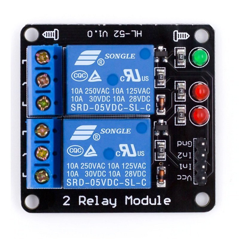
The 2 Channel 12V Relay Module is a versatile electronic component designed to control high-power devices using low-power signals. Each relay on the module can switch devices on and off with a 12V signal, making it ideal for automation and control systems. This module is commonly used in home automation, industrial control, and various DIY projects.
Explore Projects Built with 2 channel 12 V relay module
DC-DC Converter and Relay Module Power Distribution System

This circuit consists of a DC-DC converter powering a 6-channel power module, which in turn supplies 5V to a 2-relay module. The power module distributes the converted voltage to the relay module, enabling it to control external devices.
Arduino UNO Based Voltage Monitoring and Relay Control System
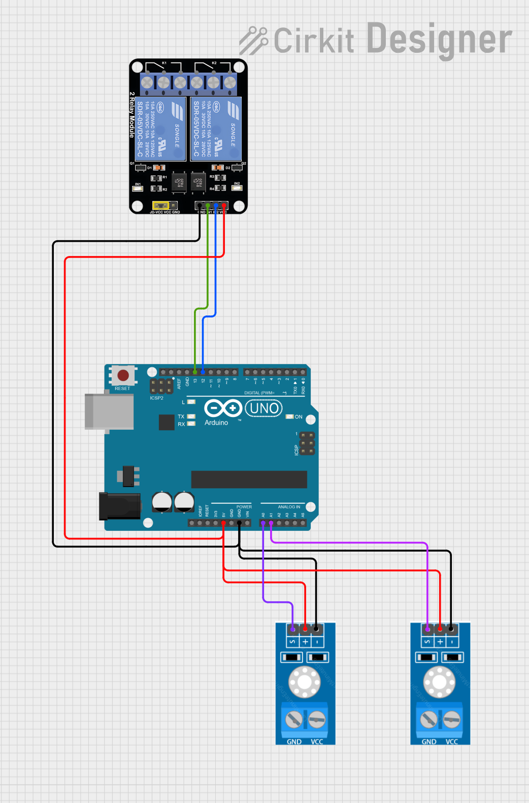
This circuit features an Arduino UNO connected to two voltage sensors and a 2-channel relay module. The Arduino monitors voltage levels through analog inputs A0 and A1, which are connected to the outputs of the voltage sensors. It controls the relay module via digital outputs D13 and D12, which are connected to the relay inputs IN1 and IN2, respectively, allowing the Arduino to switch external circuits on and off based on the voltage sensor readings.
Battery-Powered 4-Channel Relay Control with LED Indicators

This circuit consists of a 5V battery powering a 4-channel relay module, which controls four LEDs (red, yellow, green, and blue) through individual resistors. Each relay channel is activated by a corresponding SPST toggle switch, allowing manual control of the LEDs.
Arduino UNO Controlled 12V Relay System for Fan and Bulb with Battery Power
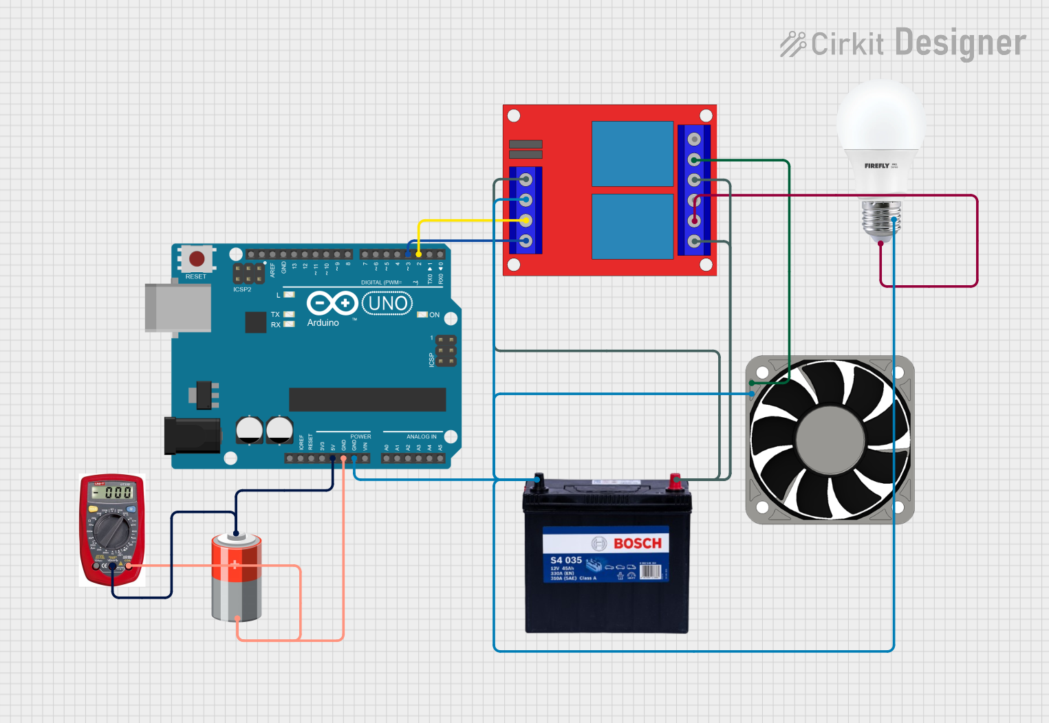
This circuit uses an Arduino UNO to control a 2-channel 12V relay module, which in turn controls a 12V fan and a bulb. The Arduino is powered by a 5V battery and cycles the fan and bulb on and off at 1-second intervals. A multimeter is connected to monitor the 5V power supply.
Explore Projects Built with 2 channel 12 V relay module
DC-DC Converter and Relay Module Power Distribution System
This circuit consists of a DC-DC converter powering a 6-channel power module, which in turn supplies 5V to a 2-relay module. The power module distributes the converted voltage to the relay module, enabling it to control external devices.
Arduino UNO Based Voltage Monitoring and Relay Control System
This circuit features an Arduino UNO connected to two voltage sensors and a 2-channel relay module. The Arduino monitors voltage levels through analog inputs A0 and A1, which are connected to the outputs of the voltage sensors. It controls the relay module via digital outputs D13 and D12, which are connected to the relay inputs IN1 and IN2, respectively, allowing the Arduino to switch external circuits on and off based on the voltage sensor readings.
Battery-Powered 4-Channel Relay Control with LED Indicators
This circuit consists of a 5V battery powering a 4-channel relay module, which controls four LEDs (red, yellow, green, and blue) through individual resistors. Each relay channel is activated by a corresponding SPST toggle switch, allowing manual control of the LEDs.
Arduino UNO Controlled 12V Relay System for Fan and Bulb with Battery Power
This circuit uses an Arduino UNO to control a 2-channel 12V relay module, which in turn controls a 12V fan and a bulb. The Arduino is powered by a 5V battery and cycles the fan and bulb on and off at 1-second intervals. A multimeter is connected to monitor the 5V power supply.
Technical Specifications
Key Technical Details
| Parameter | Value |
|---|---|
| Operating Voltage | 12V DC |
| Trigger Voltage | 5V DC |
| Relay Type | SPDT (Single Pole Double Throw) |
| Max Switching Voltage | 250V AC / 30V DC |
| Max Switching Current | 10A |
| Number of Channels | 2 |
| Dimensions | 50mm x 40mm x 20mm |
Pin Configuration and Descriptions
Input Pins
| Pin Name | Description |
|---|---|
| VCC | Connect to 5V power supply |
| GND | Ground |
| IN1 | Control signal for Relay 1 (active low) |
| IN2 | Control signal for Relay 2 (active low) |
Output Pins
| Pin Name | Description |
|---|---|
| COM1 | Common terminal for Relay 1 |
| NO1 | Normally Open terminal for Relay 1 |
| NC1 | Normally Closed terminal for Relay 1 |
| COM2 | Common terminal for Relay 2 |
| NO2 | Normally Open terminal for Relay 2 |
| NC2 | Normally Closed terminal for Relay 2 |
Usage Instructions
How to Use the Component in a Circuit
Power Supply:
- Connect the VCC pin to a 5V power supply.
- Connect the GND pin to the ground of the power supply.
Control Signals:
- Connect the IN1 pin to a digital output pin of a microcontroller (e.g., Arduino).
- Connect the IN2 pin to another digital output pin of the microcontroller.
Load Connections:
- Connect the device you want to control to the COM1 and NO1/NC1 terminals for Relay 1.
- Connect another device to the COM2 and NO2/NC2 terminals for Relay 2.
Important Considerations and Best Practices
- Ensure that the power supply voltage matches the module's operating voltage (12V DC).
- Use appropriate heat sinks or cooling mechanisms if switching high-power loads.
- Avoid switching loads that exceed the relay's maximum ratings to prevent damage.
- Use optocouplers or isolation circuits if controlling the relay module from sensitive electronics.
Example Code for Arduino UNO
/*
  Example code to control a 2 Channel 12V Relay Module using Arduino UNO.
  This code will turn on Relay 1 for 2 seconds, then turn it off and turn on
  Relay 2 for 2 seconds, and repeat the cycle.
*/

const int relay1Pin = 7; // Pin connected to IN1
const int relay2Pin = 8; // Pin connected to IN2

void setup() {
  // Initialize the relay control pins as outputs
  pinMode(relay1Pin, OUTPUT);
  pinMode(relay2Pin, OUTPUT);

  // Ensure relays are off at startup
  digitalWrite(relay1Pin, HIGH);
  digitalWrite(relay2Pin, HIGH);
}

void loop() {
  // Turn on Relay 1
  digitalWrite(relay1Pin, LOW);
  delay(2000); // Wait for 2 seconds

  // Turn off Relay 1
  digitalWrite(relay1Pin, HIGH);

  // Turn on Relay 2
  digitalWrite(relay2Pin, LOW);
  delay(2000); // Wait for 2 seconds

  // Turn off Relay 2
  digitalWrite(relay2Pin, HIGH);
}
Troubleshooting and FAQs
Common Issues Users Might Face
Relays Not Switching:
- Ensure the control signals (IN1 and IN2) are correctly connected and receiving the appropriate voltage.
- Verify that the power supply voltage is 12V DC.
Relay Module Overheating:
- Check if the load exceeds the relay's maximum current rating.
- Use heat sinks or cooling mechanisms if necessary.
Interference with Microcontroller:
- Use optocouplers or isolation circuits to prevent electrical noise from affecting the microcontroller.
Solutions and Tips for Troubleshooting
- Check Connections: Ensure all connections are secure and correctly oriented.
- Measure Voltages: Use a multimeter to verify the voltages at the VCC, GND, IN1, and IN2 pins.
- Test Relays Individually: Test each relay separately to isolate the issue.
- Use External Power Supply: If the microcontroller's power supply is insufficient, use an external power supply for the relay module.
By following this documentation, users can effectively integrate the 2 Channel 12V Relay Module into their projects, ensuring reliable and efficient control of high-power devices.