How to Use Adafruit DRV8833 DC-Stepper Motor Driver: Examples, Pinouts, and Specs
Introduction
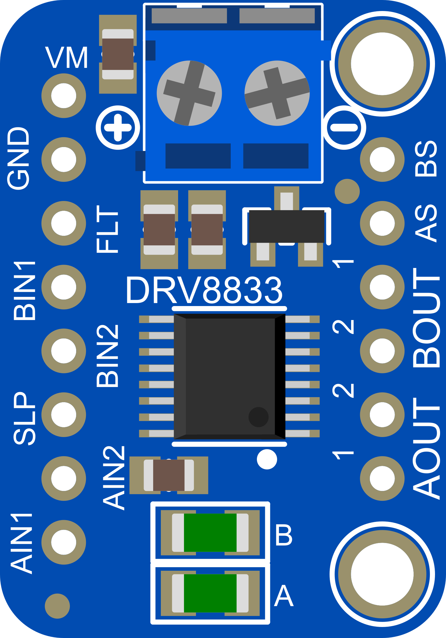
The Adafruit DRV8833 is a versatile motor driver capable of driving two DC motors or one bipolar stepper motor. It is based on the Texas Instruments DRV8833 motor driver IC and is designed for use in small robotics, hobbyist projects, and educational applications. The board's compact size, combined with its robust protection features, makes it an excellent choice for projects where space and reliability are critical.
Explore Projects Built with Adafruit DRV8833 DC-Stepper Motor Driver
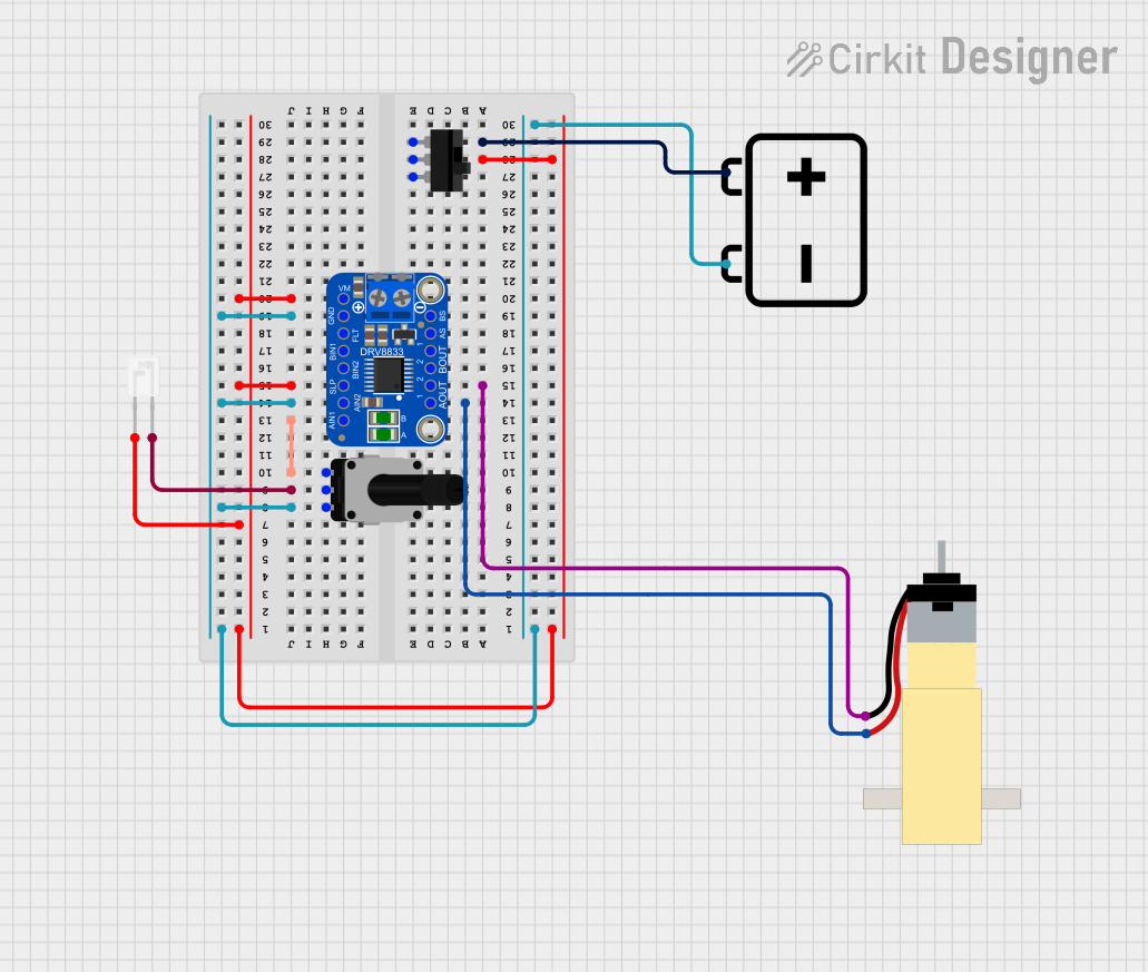
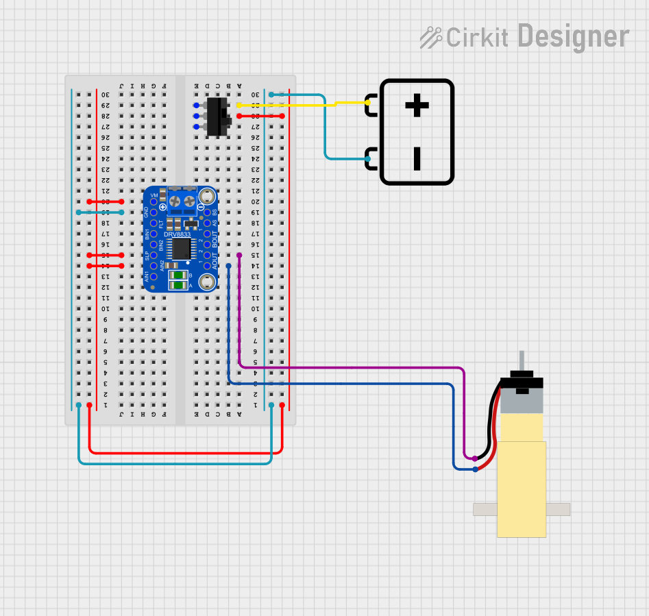

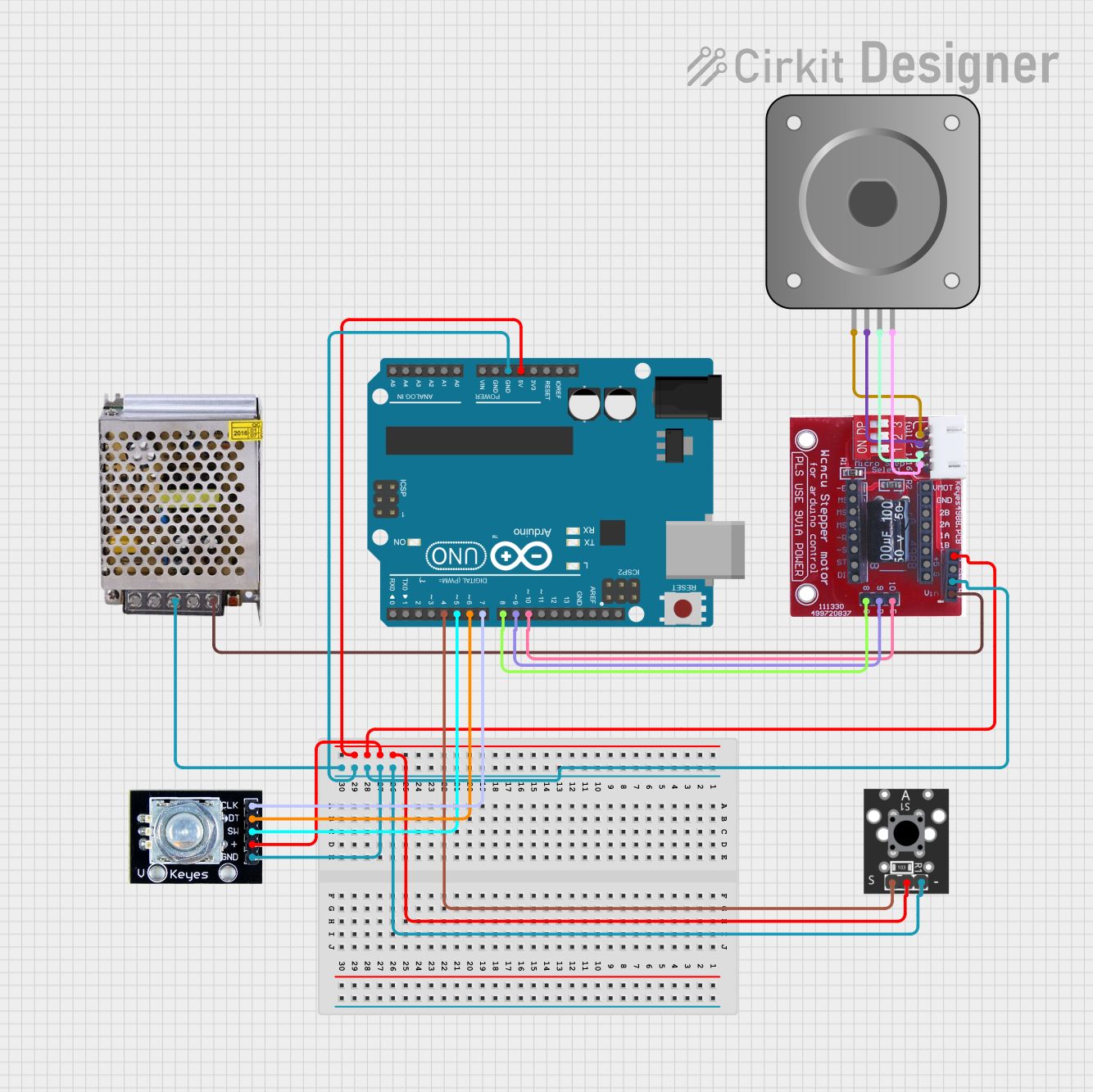
Explore Projects Built with Adafruit DRV8833 DC-Stepper Motor Driver
Common Applications and Use Cases
- Small robotics vehicles
- Hobbyist projects involving motor control
- Educational platforms for teaching electronics and robotics
- Prototyping for devices that require actuation
Technical Specifications
Key Technical Details
- Motor Voltage (VMOT): 2.7V to 10.8V
- Output Current: 1.5A per channel (peak) or 1.2A continuous
- Logic Voltage (VCC): 2.7V to 5.5V
- H-Bridge configuration for bidirectional motor control
- Over-current and over-temperature protection
- Under-voltage lockout
- 4-layer, 2oz copper PCB for improved heat dissipation
Pin Configuration and Descriptions
| Pin Name | Description |
|---|---|
| VMOT | Motor power supply (2.7V to 10.8V) |
| GND | Ground connection |
| AIN1 | Input control for motor A, channel 1 |
| AIN2 | Input control for motor A, channel 2 |
| BIN1 | Input control for motor B, channel 1 |
| BIN2 | Input control for motor B, channel 2 |
| AOUT1 | Output for motor A, channel 1 |
| AOUT2 | Output for motor A, channel 2 |
| BOUT1 | Output for motor B, channel 1 |
| BOUT2 | Output for motor B, channel 2 |
| VCC | Logic power supply (2.7V to 5.5V) |
| FAULT | Fault status output (active-low) |
Usage Instructions
How to Use the Component in a Circuit
- Connect the motor(s) to the AOUT1/AOUT2 and BOUT1/BOUT2 if using two DC motors, or to both A and B outputs if using a stepper motor.
- Apply the motor power supply to VMOT and ground to GND.
- Connect the logic power supply to VCC and ground to GND.
- Use the AIN1/AIN2 and BIN1/BIN2 pins to control the motors via a microcontroller or other control logic.
- Monitor the FAULT pin to detect any fault conditions.
Important Considerations and Best Practices
- Ensure that the power supply voltage does not exceed the specified limits for VMOT and VCC.
- Do not exceed the continuous current rating of 1.2A per channel to prevent overheating.
- Use a decoupling capacitor close to the VMOT and VCC pins to minimize voltage spikes.
- Avoid running motors at stall current as this can quickly lead to overheating and damage.
- Always check the motor driver for any signs of overheating during operation.
Example Code for Arduino UNO
// Example code to control a DC motor with the Adafruit DRV8833

#include <Arduino.h>

// Define control pins for Motor A
const int AIN1 = 2;
const int AIN2 = 3;

void setup() {
  // Set the motor control pins as outputs
  pinMode(AIN1, OUTPUT);
  pinMode(AIN2, OUTPUT);
}

void loop() {
  // Spin the motor in one direction
  digitalWrite(AIN1, HIGH);
  digitalWrite(AIN2, LOW);
  delay(1000);

  // Stop the motor
  digitalWrite(AIN1, LOW);
  digitalWrite(AIN2, LOW);
  delay(1000);

  // Spin the motor in the opposite direction
  digitalWrite(AIN1, LOW);
  digitalWrite(AIN2, HIGH);
  delay(1000);

  // Stop the motor
  digitalWrite(AIN1, LOW);
  digitalWrite(AIN2, LOW);
  delay(1000);
}
Troubleshooting and FAQs
Common Issues
- Motor not moving: Check connections, ensure power supply is within specifications, and verify control signals.
- Overheating: Reduce the load on the motor or improve cooling.
- Intermittent operation: Check for loose connections and ensure that the power supply is stable.
Solutions and Tips for Troubleshooting
- If the FAULT pin is active, check for over-current or over-temperature conditions and address them.
- Use a multimeter to verify that the control signals are reaching the driver inputs.
- Ensure that the logic voltage (VCC) is within the specified range and stable.
FAQs
Q: Can I drive two stepper motors with one DRV8833 board? A: No, the DRV8833 can drive only one stepper motor or two DC motors.
Q: What should I do if the motor driver gets hot during operation? A: Ensure that the current through the motor driver does not exceed the continuous rating and consider adding a heat sink or improving airflow around the driver.
Q: Can I use the DRV8833 with a 3.3V logic level microcontroller? A: Yes, the DRV8833 is compatible with logic levels from 2.7V to 5.5V.
Remember, this documentation is a starting point for using the Adafruit DRV8833 motor driver. Always consult the datasheet and additional resources for more detailed information.