How to Use Timer theben: Examples, Pinouts, and Specs
Introduction
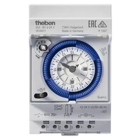
The Timer Theben is a programmable timer switch designed for controlling electrical devices based on predefined time schedules. Manufactured by Theben, this component is widely used in applications requiring precise time-based automation. It is particularly popular in lighting systems, HVAC (Heating, Ventilation, and Air Conditioning) systems, and other energy management solutions. By automating device operation, the Timer Theben helps improve energy efficiency and reduce manual intervention.
Explore Projects Built with Timer theben
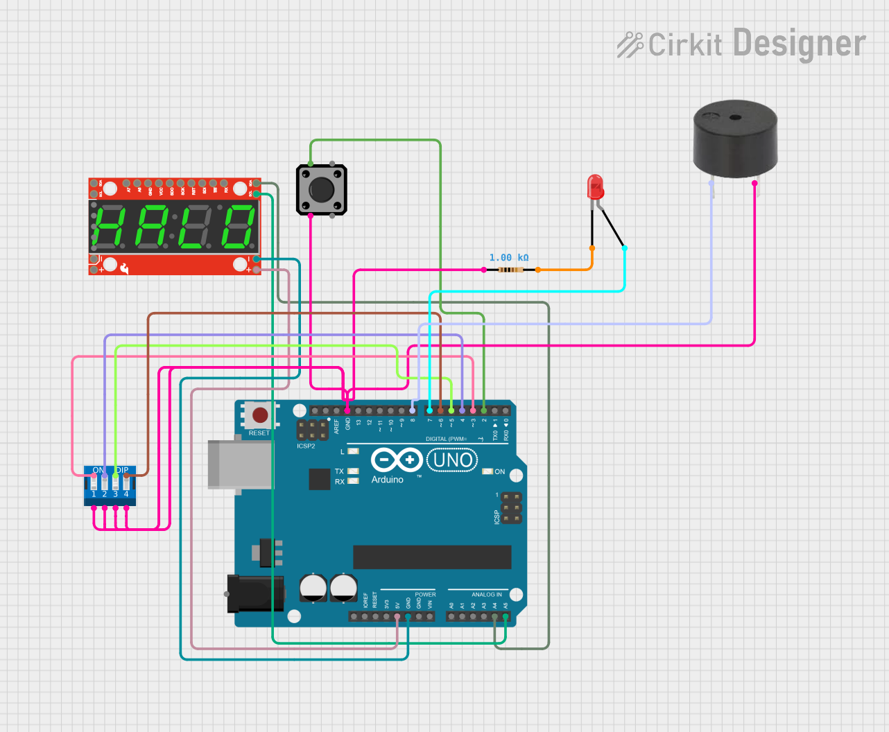
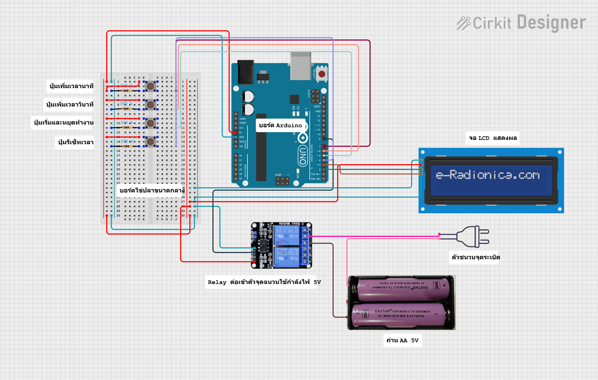
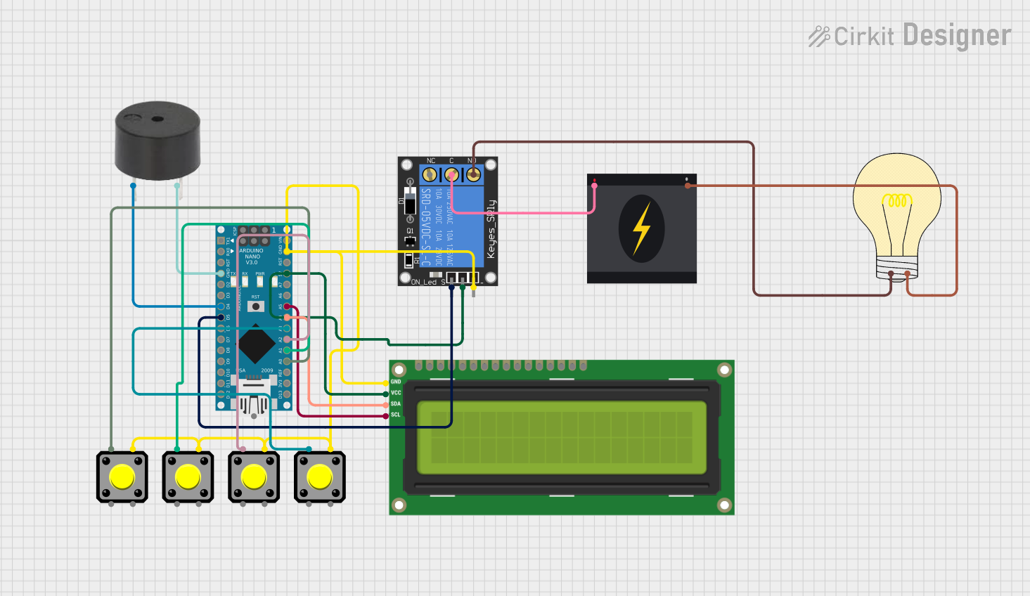
Explore Projects Built with Timer theben
Common Applications and Use Cases
- Lighting Control: Automating indoor and outdoor lighting systems.
- HVAC Systems: Scheduling heating, cooling, and ventilation systems for optimal energy use.
- Industrial Automation: Controlling machinery or processes based on time intervals.
- Irrigation Systems: Scheduling water pumps for agricultural or landscaping purposes.
- Home Automation: Managing appliances like water heaters or coffee machines.
Technical Specifications
The Timer Theben is available in various models, but the following are general specifications for a typical programmable timer switch:
| Parameter | Specification |
|---|---|
| Power Supply Voltage | 230 V AC, 50/60 Hz |
| Power Consumption | < 1 W |
| Switching Capacity | 16 A / 250 V AC (resistive load) |
| Programming | Daily or weekly schedules |
| Backup Power | Integrated battery for memory retention |
| Operating Temperature | -10°C to +50°C |
| Display | LCD for programming and status display |
| Mounting | DIN rail or wall-mounted (model-specific) |
Pin Configuration and Descriptions
The Timer Theben typically features screw terminals for wiring. Below is a general description of the terminal connections:
| Terminal | Description |
|---|---|
| L | Live input (230 V AC) |
| N | Neutral input |
| 1 | Normally open (NO) contact for load connection |
| 2 | Common terminal for the relay |
| 3 | Normally closed (NC) contact for load connection |
Note: Always refer to the specific model's datasheet for exact terminal configurations.
Usage Instructions
How to Use the Timer Theben in a Circuit
Wiring:
- Connect the live wire (L) and neutral wire (N) to the respective input terminals of the timer.
- Connect the load (e.g., a light or motor) to the output terminals (1 and 2 for normally open, or 2 and 3 for normally closed).
- Ensure all connections are secure and comply with local electrical codes.
Programming:
- Use the LCD interface and buttons to set the desired time schedules.
- Select between daily or weekly programming modes, depending on your application.
- Save the schedule to the timer's memory.
Testing:
- After programming, test the timer by observing its operation over a short period.
- Verify that the connected load turns on and off according to the programmed schedule.
Important Considerations and Best Practices
- Safety First: Always disconnect power before wiring or modifying the timer.
- Load Compatibility: Ensure the connected load does not exceed the timer's switching capacity (16 A / 250 V AC).
- Backup Power: Check the integrated battery periodically to ensure memory retention during power outages.
- Environmental Conditions: Install the timer in a location within its operating temperature range (-10°C to +50°C) and away from moisture or direct sunlight.
Example: Connecting Timer Theben to an Arduino UNO
While the Timer Theben is primarily a standalone device, it can be integrated with an Arduino UNO for advanced automation. Below is an example of how to use the timer's relay output to control an Arduino input pin:
Circuit Diagram
- Connect the Timer Theben's normally open (NO) terminal to an Arduino digital input pin (e.g., pin 2).
- Connect the common terminal (COM) to the Arduino's ground (GND).
Arduino Code
// Example code to read the Timer Theben's relay output with Arduino
const int timerPin = 2;  // Digital pin connected to Timer Theben's NO terminal
const int ledPin = 13;   // Built-in LED for status indication

void setup() {
  pinMode(timerPin, INPUT);  // Set timerPin as input
  pinMode(ledPin, OUTPUT);   // Set ledPin as output
  Serial.begin(9600);        // Initialize serial communication
}

void loop() {
  int timerState = digitalRead(timerPin);  // Read the state of the timer's relay

  if (timerState == HIGH) {
    digitalWrite(ledPin, HIGH);  // Turn on LED if timer is active
    Serial.println("Timer is ON");
  } else {
    digitalWrite(ledPin, LOW);   // Turn off LED if timer is inactive
    Serial.println("Timer is OFF");
  }

  delay(500);  // Wait for 500 ms before reading again
}
Note: Ensure the Timer Theben's relay output is properly isolated from the Arduino to avoid damage.
Troubleshooting and FAQs
Common Issues and Solutions
Timer Does Not Power On:
- Check the power supply voltage and connections to the L and N terminals.
- Verify that the circuit breaker or fuse is not tripped.
Load Does Not Turn On/Off:
- Ensure the load is connected to the correct output terminals (NO or NC).
- Verify that the programmed schedule is active and correctly set.
Timer Loses Settings After Power Outage:
- Check the integrated battery and replace it if necessary.
- Ensure the timer is not exposed to extreme temperatures that could affect battery performance.
Display Is Not Visible:
- Confirm that the timer is receiving power.
- Check for any obstructions or damage to the LCD.
FAQs
Q: Can the Timer Theben handle inductive loads like motors?
A: Yes, but ensure the inductive load does not exceed the timer's switching capacity. Use a contactor for higher loads.Q: How long does the backup battery last?
A: The integrated battery typically lasts several years, depending on usage and environmental conditions.Q: Can I use the Timer Theben outdoors?
A: Only if the timer is installed in a weatherproof enclosure and within its operating temperature range.Q: Is it possible to override the programmed schedule?
A: Yes, most Timer Theben models include a manual override function for temporary control.
By following this documentation, users can effectively utilize the Timer Theben for a wide range of time-based automation tasks.