
How to Use Heart Pulse Sensor: Examples, Pinouts, and Specs
 Design with Heart Pulse Sensor in Cirkit Designer
Introduction
The Heart Pulse Sensor is a compact and efficient device designed to detect and measure the heartbeat by analyzing the blood flow through the skin. It operates using photoplethysmography (PPG), a non-invasive optical technique that measures changes in blood volume. This sensor is widely used in health monitoring applications, fitness trackers, and biofeedback systems. Its ease of use and compatibility with microcontrollers make it a popular choice for both hobbyists and professionals.
Explore Projects Built with Heart Pulse Sensor
 Open Project in Cirkit Designer
 Open Project in Cirkit Designer
 Open Project in Cirkit Designer
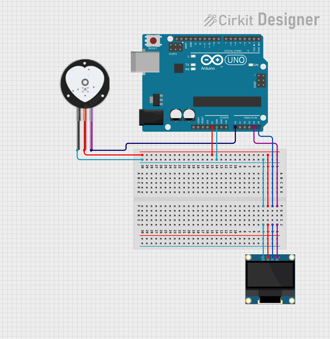 Open Project in Cirkit Designer
Explore Projects Built with Heart Pulse Sensor
Open Project in Cirkit DesignerOpen Project in Cirkit DesignerOpen Project in Cirkit DesignerOpen Project in Cirkit DesignerCommon Applications:
- Fitness trackers and wearable devices
- Health monitoring systems
- Biofeedback and stress management tools
- Educational and research projects
Technical Specifications
The Heart Pulse Sensor is designed for simplicity and reliability. Below are its key technical details:
General Specifications:
- Operating Voltage: 3.3V to 5V
- Operating Current: 4mA (typical)
- Output Signal: Analog
- Sensor Type: Optical (PPG-based)
- Dimensions: ~1 inch diameter (varies by manufacturer)
Pin Configuration:
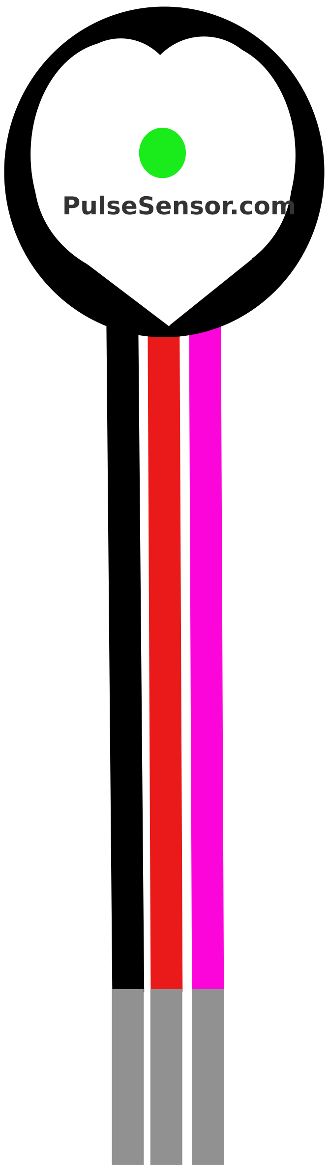
The Heart Pulse Sensor typically has three pins for connection. The table below describes each pin:
| Pin | Name | Description |
|---|---|---|
| 1 | VCC | Power supply pin. Connect to 3.3V or 5V depending on your microcontroller. |
| 2 | GND | Ground pin. Connect to the ground of your circuit. |
| 3 | Signal | Analog output pin. Provides a voltage signal proportional to the heartbeat. |
Usage Instructions
How to Use the Heart Pulse Sensor in a Circuit:
Connect the Pins:
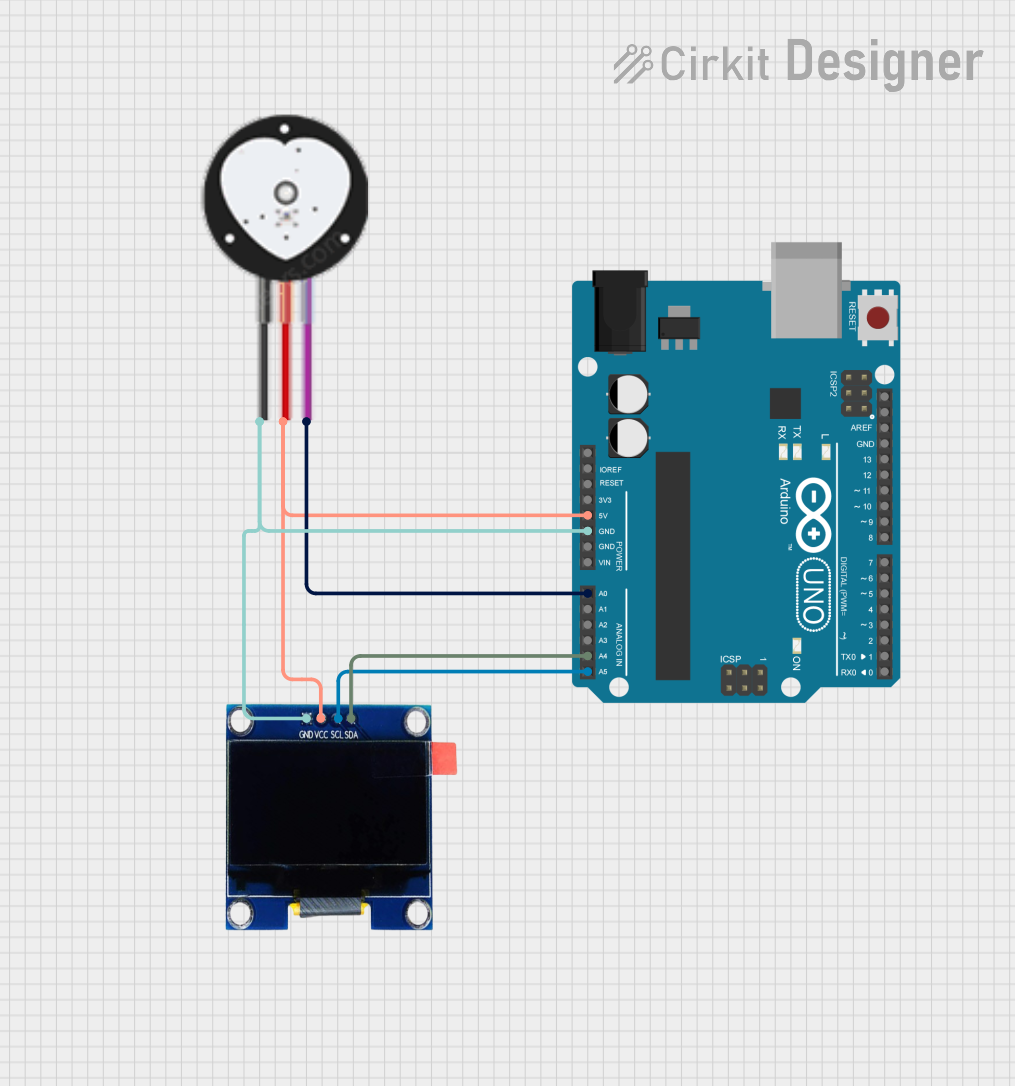
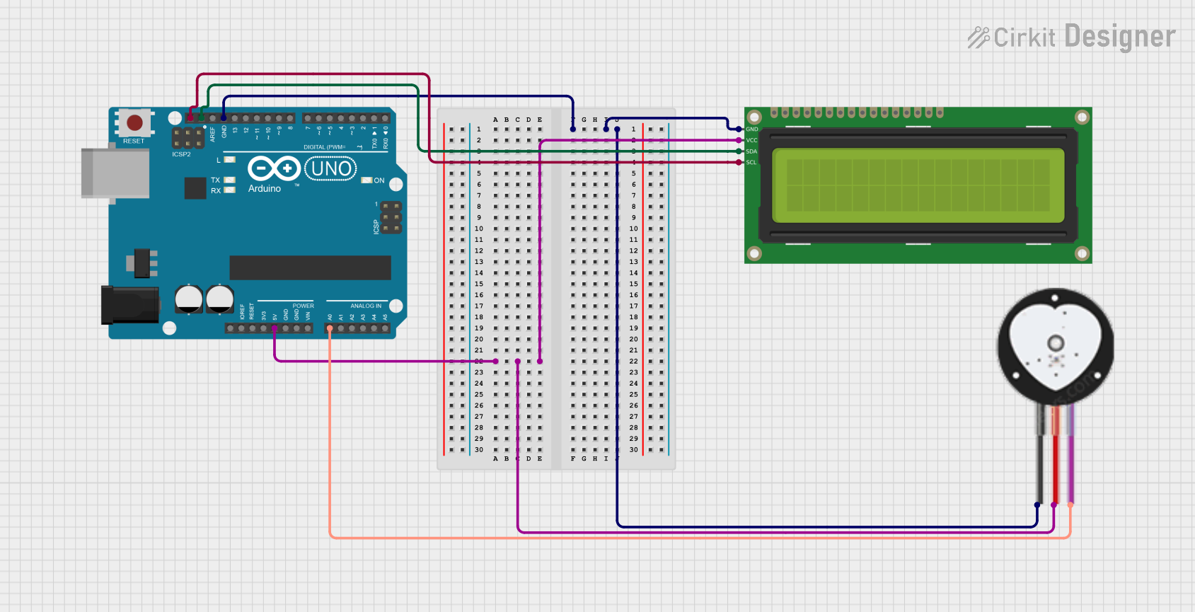
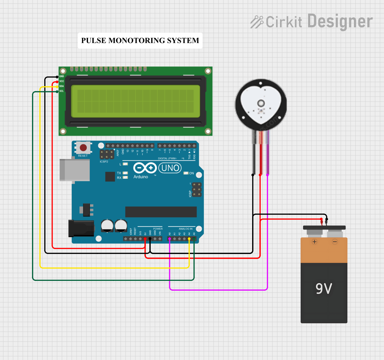
- Connect the VCC pin to the 3.3V or 5V power supply of your microcontroller.
- Connect the GND pin to the ground of your circuit.
- Connect the Signal pin to an analog input pin on your microcontroller.
Placement of the Sensor:
- Place the sensor on a fingertip or earlobe for optimal results.
- Ensure the sensor is securely positioned to minimize movement artifacts.
Read the Signal:
- Use an analog-to-digital converter (ADC) on your microcontroller to read the signal from the Signal pin.
- The output signal will vary in voltage corresponding to the heartbeat.
Important Considerations:
- Avoid excessive movement during measurement to reduce noise and inaccuracies.
- Ensure proper skin contact with the sensor for reliable readings.
- Use a low-pass filter in your circuit or software to smooth out the signal and remove noise.
Example Code for Arduino UNO:
Below is an example of how to use the Heart Pulse Sensor with an Arduino UNO:
// Heart Pulse Sensor Example Code for Arduino UNO
// Reads the analog signal from the sensor and displays the values in the Serial Monitor.

const int pulsePin = A0; // Connect the Signal pin of the sensor to A0
int pulseValue = 0;      // Variable to store the analog value

void setup() {
  Serial.begin(9600); // Initialize serial communication at 9600 baud
  pinMode(pulsePin, INPUT); // Set the pulsePin as an input
}

void loop() {
  pulseValue = analogRead(pulsePin); // Read the analog value from the sensor
  Serial.print("Pulse Value: ");     // Print a label for the value
  Serial.println(pulseValue);        // Print the pulse value to the Serial Monitor
  delay(10);                         // Small delay for stability
}
Notes:
- Open the Serial Monitor in the Arduino IDE to view the pulse values.
- You can process the raw data further to calculate the heart rate in beats per minute (BPM).
Troubleshooting and FAQs
Common Issues and Solutions:
No Signal Detected:
- Cause: Loose connections or improper placement of the sensor.
- Solution: Check all connections and ensure the sensor is securely placed on the skin.
Noisy or Fluctuating Readings:
- Cause: Excessive movement or poor skin contact.
- Solution: Minimize movement and ensure proper contact with the skin. Use a low-pass filter to reduce noise.
Inconsistent Heart Rate:
- Cause: Environmental light interference or incorrect power supply voltage.
- Solution: Shield the sensor from ambient light and ensure the power supply voltage matches the sensor's requirements.
FAQs:
Q: Can I use the Heart Pulse Sensor with a 3.3V microcontroller?
A: Yes, the sensor is compatible with both 3.3V and 5V systems.Q: How do I calculate BPM from the sensor's output?
A: You can process the analog signal to detect peaks (heartbeats) and calculate the time interval between them. Use this interval to compute BPM.Q: Can the sensor be used on other body parts?
A: Yes, the sensor can be used on the earlobe or wrist, but the fingertip typically provides the most reliable readings.
By following this documentation, you can effectively integrate the Heart Pulse Sensor into your projects and achieve accurate heartbeat measurements.