
How to Use Amplifier: Examples, Pinouts, and Specs
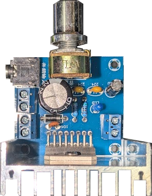
 Design with Amplifier in Cirkit Designer
Introduction
An amplifier is an electronic device designed to increase the power, voltage, or current of an input signal. It is a fundamental component in electronics, widely used in applications such as audio equipment, radio transmission, and signal processing. Amplifiers are essential for enhancing weak signals to levels suitable for further processing or output.
Common applications of amplifiers include:
- Audio systems (e.g., speakers, headphones, and microphones)
- Radio frequency (RF) communication systems
- Signal conditioning in sensors and instrumentation
- Medical devices such as ECG and EEG machines
- Industrial control systems
Explore Projects Built with Amplifier
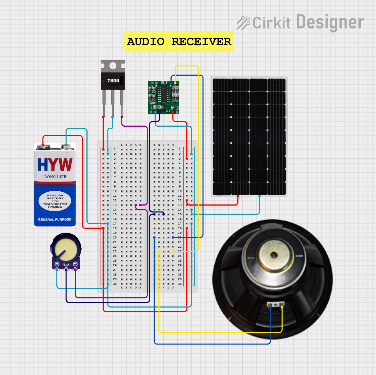 Open Project in Cirkit Designer
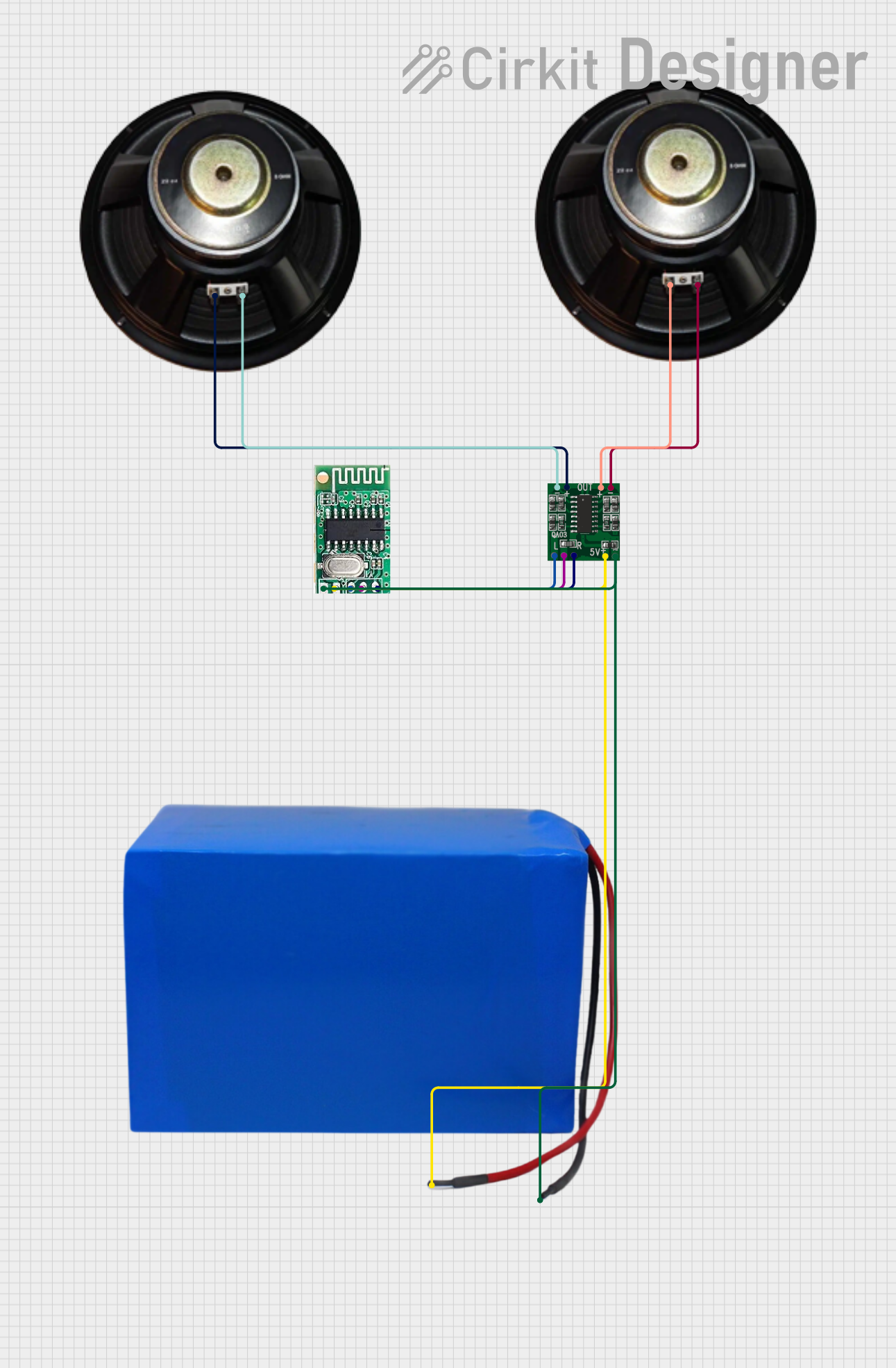 Open Project in Cirkit Designer
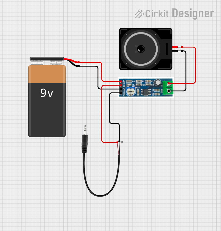 Open Project in Cirkit Designer
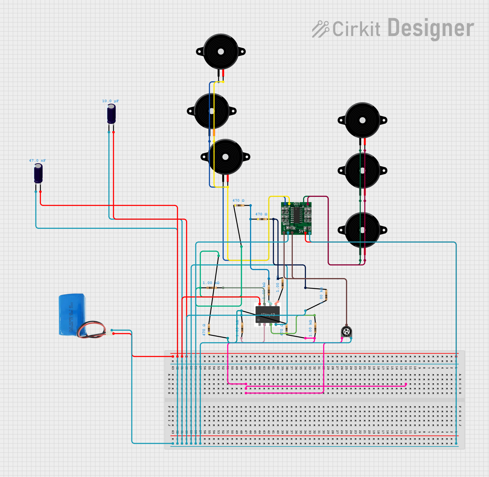 Open Project in Cirkit Designer
Explore Projects Built with Amplifier
Open Project in Cirkit DesignerOpen Project in Cirkit DesignerOpen Project in Cirkit DesignerOpen Project in Cirkit DesignerTechnical Specifications
The technical specifications of an amplifier can vary depending on its type and application. Below are general specifications for a typical operational amplifier (op-amp), which is a common type of amplifier:
General Specifications
| Parameter | Value/Range | Description |
|---|---|---|
| Supply Voltage (Vcc) | ±5V to ±15V | Voltage required to power the amplifier |
| Input Voltage Range | -Vcc to +Vcc | Acceptable input signal range |
| Gain | 1 to 1,000,000 (varies by type) | Ratio of output signal to input signal |
| Bandwidth | 10 Hz to several MHz | Frequency range the amplifier can handle |
| Input Impedance | 1 MΩ to 10 MΩ | Resistance at the input terminal |
| Output Impedance | 10 Ω to 100 Ω | Resistance at the output terminal |
| Power Consumption | Low to Moderate | Depends on the application |
Pin Configuration (Example: 8-Pin Op-Amp IC)
| Pin Number | Pin Name | Description |
|---|---|---|
| 1 | Offset Null | Used to adjust the offset voltage |
| 2 | Inverting Input | Input where the signal is inverted |
| 3 | Non-Inverting Input | Input where the signal is not inverted |
| 4 | V- (Ground) | Negative power supply or ground connection |
| 5 | Offset Null | Used to adjust the offset voltage |
| 6 | Output | Amplified output signal |
| 7 | V+ (Vcc) | Positive power supply connection |
| 8 | NC (No Connect) | Not connected internally (varies by IC model) |
Usage Instructions
To use an amplifier in a circuit, follow these steps:
- Power Supply: Connect the amplifier to an appropriate power supply. Ensure the supply voltage matches the amplifier's specifications (e.g., ±5V to ±15V for an op-amp).
- Input Signal: Connect the input signal to the appropriate input pin (inverting or non-inverting). Use a coupling capacitor if necessary to block DC components.
- Feedback Network: For op-amps, design a feedback network (resistors and/or capacitors) to set the desired gain and stability.
- Output Load: Connect the output pin to the load (e.g., speaker, sensor, or another circuit). Ensure the load impedance matches the amplifier's output impedance.
- Bypass Capacitors: Place bypass capacitors near the power supply pins to reduce noise and improve stability.
Example: Connecting an Op-Amp to an Arduino UNO
Below is an example of using an op-amp to amplify a sensor signal and read it with an Arduino UNO:
Circuit Description
- The op-amp is configured in a non-inverting configuration with a gain of 10.
- The amplified signal is fed into an analog input pin of the Arduino.
Arduino Code
// Amplifier Example with Arduino UNO
// Reads an amplified signal from an op-amp and displays the value via Serial Monitor

const int analogPin = A0; // Analog pin connected to the op-amp output

void setup() {
  Serial.begin(9600); // Initialize serial communication at 9600 baud
}

void loop() {
  int sensorValue = analogRead(analogPin); // Read the amplified signal
  float voltage = sensorValue * (5.0 / 1023.0); // Convert ADC value to voltage
  Serial.print("Amplified Voltage: ");
  Serial.print(voltage);
  Serial.println(" V");
  delay(500); // Wait for 500ms before the next reading
}
Best Practices
- Use proper decoupling capacitors near the power supply pins to minimize noise.
- Avoid exceeding the input voltage range to prevent damage to the amplifier.
- Ensure the feedback network is stable to avoid oscillations.
- Match the load impedance to the amplifier's output impedance for optimal performance.
Troubleshooting and FAQs
Common Issues
No Output Signal:
- Check the power supply connections and ensure the amplifier is powered correctly.
- Verify that the input signal is within the acceptable range.
Distorted Output:
- Ensure the amplifier is not saturating by reducing the input signal amplitude.
- Check the feedback network for incorrect resistor or capacitor values.
Oscillations or Noise:
- Add bypass capacitors near the power supply pins.
- Verify the feedback network design for stability.
Low Gain:
- Check the feedback resistor values and ensure they are set correctly for the desired gain.
- Verify that the input signal is connected to the correct input pin.
FAQs
Q: Can I use an amplifier to boost a digital signal?
A: Amplifiers are typically used for analog signals. For digital signals, use a logic level shifter or a digital buffer.
Q: What is the difference between an inverting and non-inverting amplifier?
A: An inverting amplifier inverts the phase of the input signal, while a non-inverting amplifier maintains the same phase.
Q: How do I calculate the gain of an op-amp?
A: For a non-inverting amplifier, gain = 1 + (Rf / Rin), where Rf is the feedback resistor and Rin is the input resistor. For an inverting amplifier, gain = - (Rf / Rin).
Q: Can I use an amplifier with a single power supply?
A: Yes, many amplifiers support single-supply operation. Ensure the input signal is biased appropriately within the amplifier's input range.
By following this documentation, you can effectively use an amplifier in your electronic projects and troubleshoot common issues.