How to Use 4×4 Keypad2: Examples, Pinouts, and Specs
JJY KEYPAD_4X4 Documentation
1. Introduction
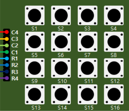
The JJY KEYPAD_4X4 is a 4×4 matrix keypad consisting of 16 tactile push buttons arranged in a grid of 4 rows and 4 columns. This keypad is widely used in electronic devices for user input, such as entering numeric data, passwords, or commands. Its compact design and ease of integration make it a popular choice for hobbyists and professionals alike.
Common Applications:
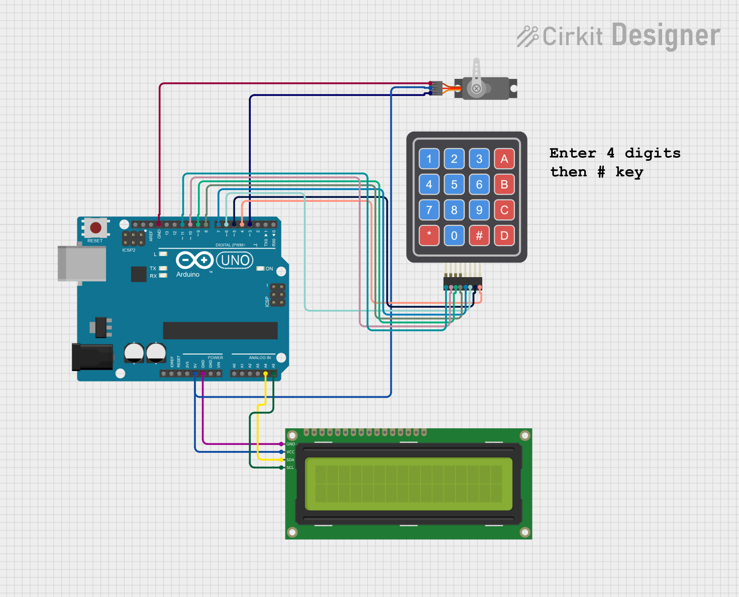
- Security systems (e.g., password entry for door locks)
- Home automation control panels
- Calculator-style input devices
- Menu navigation in embedded systems
- Robotics control interfaces
The KEYPAD_4X4 is compatible with microcontrollers like Arduino, Raspberry Pi, and other development boards, making it a versatile component for a variety of projects.
2. Technical Specifications
The following table outlines the key technical details of the JJY KEYPAD_4X4:
| Parameter | Specification |
|---|---|
| Manufacturer | JJY |
| Part ID | KEYPAD_4X4 |
| Number of Buttons | 16 (4 rows × 4 columns) |
| Operating Voltage | 3.3V to 5V |
| Maximum Current | 20mA per button |
| Button Type | Tactile push buttons |
| Connector Type | 8-pin header (row and column lines) |
| Dimensions | 70mm × 70mm × 10mm |
| Operating Temperature | -20°C to 70°C |
| Weight | ~20g |
Pin Configuration and Descriptions
The KEYPAD_4X4 has 8 pins, which correspond to the 4 rows and 4 columns of the keypad matrix. The pinout is as follows:
| Pin Number | Label | Description |
|---|---|---|
| 1 | R1 | Row 1 |
| 2 | R2 | Row 2 |
| 3 | R3 | Row 3 |
| 4 | R4 | Row 4 |
| 5 | C1 | Column 1 |
| 6 | C2 | Column 2 |
| 7 | C3 | Column 3 |
| 8 | C4 | Column 4 |
3. Usage Instructions
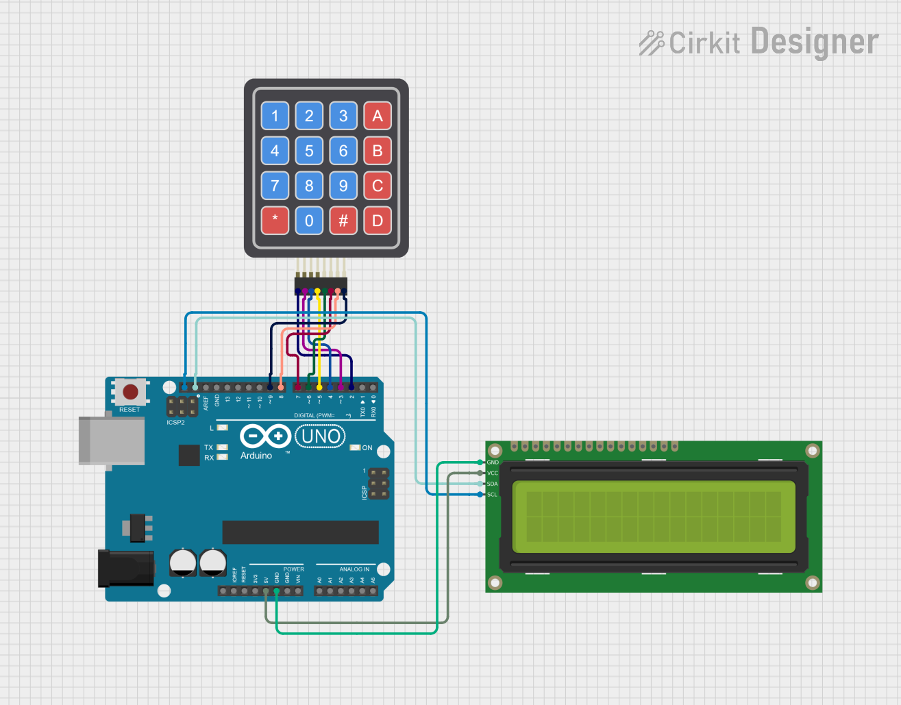
Connecting the Keypad to an Arduino UNO
To use the KEYPAD_4X4 with an Arduino UNO, follow these steps:
Wiring the Keypad:
- Connect the 8 pins of the keypad to 8 digital pins on the Arduino UNO. For example:
- R1 → D2
- R2 → D3
- R3 → D4
- R4 → D5
- C1 → D6
- C2 → D7
- C3 → D8
- C4 → D9
- Connect the 8 pins of the keypad to 8 digital pins on the Arduino UNO. For example:
Install the Keypad Library:
- Open the Arduino IDE.
- Go to Sketch > Include Library > Manage Libraries.
- Search for "Keypad" and install the library by Mark Stanley and Alexander Brevig.
Write the Code:
- Use the following example code to read button presses from the keypad:
#include <Keypad.h>

// Define the rows and columns of the keypad
const byte ROWS = 4; // Four rows
const byte COLS = 4; // Four columns

// Define the keymap for the keypad
char keys[ROWS][COLS] = {
  {'1', '2', '3', 'A'},
  {'4', '5', '6', 'B'},
  {'7', '8', '9', 'C'},
  {'*', '0', '#', 'D'}
};

// Define the row and column pins connected to the Arduino
byte rowPins[ROWS] = {2, 3, 4, 5}; // Connect to R1, R2, R3, R4
byte colPins[COLS] = {6, 7, 8, 9}; // Connect to C1, C2, C3, C4

// Create the Keypad object
Keypad keypad = Keypad(makeKeymap(keys), rowPins, colPins, ROWS, COLS);

void setup() {
  Serial.begin(9600); // Initialize serial communication
  Serial.println("4x4 Keypad Test");
}

void loop() {
  char key = keypad.getKey(); // Read the key pressed
  if (key) {
    Serial.print("Key Pressed: ");
    Serial.println(key); // Print the key to the Serial Monitor
  }
}
- Upload the Code:
- Connect the Arduino UNO to your computer.
- Upload the code to the Arduino using the Arduino IDE.
- Open the Serial Monitor to view the key presses.
Important Considerations:
- Ensure the keypad is securely connected to the Arduino to avoid loose connections.
- Use pull-up or pull-down resistors if necessary to stabilize the input signals.
- Avoid pressing multiple buttons simultaneously, as this may cause ghosting (unintended key presses).
4. Troubleshooting and FAQs
Common Issues and Solutions
| Issue | Possible Cause | Solution |
|---|---|---|
| No key presses are detected | Loose or incorrect wiring | Check and secure all connections. |
| Incorrect key is displayed | Keymap mismatch in the code | Verify and update the keymap array. |
| Multiple keys are detected at once | Ghosting due to simultaneous presses | Avoid pressing multiple keys at once. |
| Serial Monitor shows garbage data | Incorrect baud rate in Serial Monitor | Set the baud rate to 9600. |
Frequently Asked Questions
Q1: Can I use the KEYPAD_4X4 with a 3.3V microcontroller?
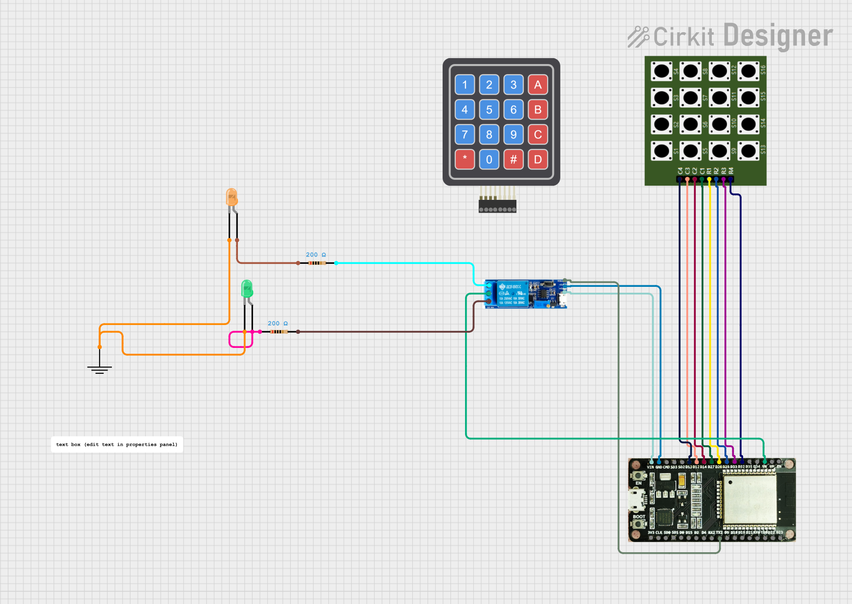
A1: Yes, the keypad operates within a voltage range of 3.3V to 5V, making it compatible with 3.3V microcontrollers like ESP32 or Raspberry Pi Pico.
Q2: How do I debounce the keypad inputs?
A2: The Keypad library includes built-in debouncing, so you don't need to implement it manually. However, if you experience issues, you can add a small delay (e.g., delay(50)) after detecting a key press.
Q3: Can I use this keypad for alphanumeric input?
A3: Yes, the keypad supports alphanumeric input. You can customize the keymap array to include letters, numbers, or symbols as needed.
Q4: What is the lifespan of the buttons?
A4: The tactile buttons are rated for approximately 1 million presses, ensuring long-term durability.
5. Conclusion
The JJY KEYPAD_4X4 is a reliable and versatile input device for a wide range of electronic projects. Its simple design, compatibility with popular microcontrollers, and ease of use make it an excellent choice for both beginners and experienced developers. By following the instructions and best practices outlined in this documentation, you can seamlessly integrate the keypad into your projects and unlock its full potential.
For further assistance, refer to the official JJY documentation or contact customer support. Happy building!
Explore Projects Built with 4×4 Keypad2

Explore Projects Built with 4×4 Keypad2