How to Use GY-53 VL53L0X: Examples, Pinouts, and Specs
Introduction
The GY-53 VL53L0X is a time-of-flight (ToF) distance sensor module that utilizes laser technology to measure distances with high accuracy. It is capable of measuring distances ranging from 30mm to 2 meters. The sensor operates by emitting a laser pulse and calculating the time it takes for the pulse to reflect back, ensuring precise and reliable measurements.
This module is widely used in applications such as:
- Robotics for obstacle detection and navigation
- Automation systems for proximity sensing
- Drones for altitude measurement
- IoT devices requiring distance measurement
- Industrial equipment for object detection
Explore Projects Built with GY-53 VL53L0X


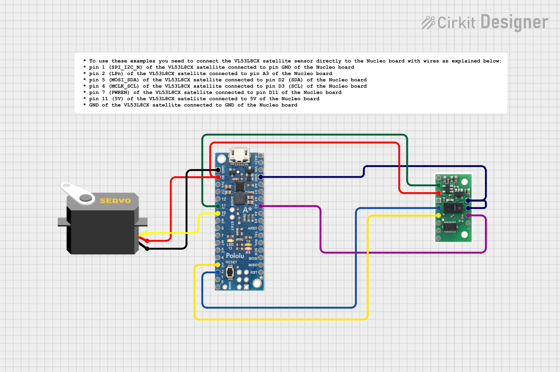
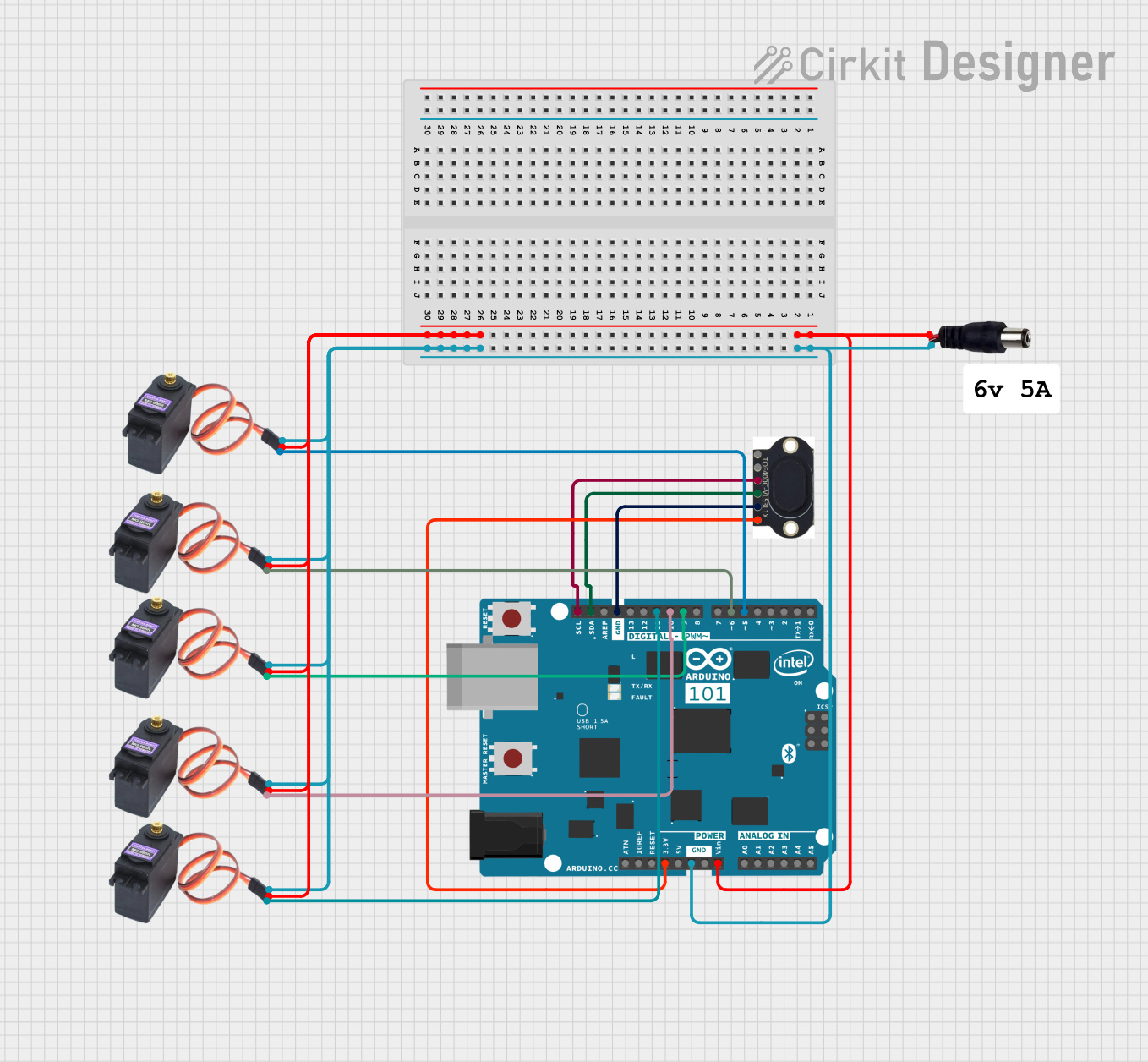
Explore Projects Built with GY-53 VL53L0X
Technical Specifications
The GY-53 VL53L0X module is built around the VL53L0X sensor, which is a compact and efficient ToF sensor. Below are the key technical details:
| Parameter | Specification |
|---|---|
| Operating Voltage | 3.3V to 5V |
| Operating Current | ~10mA |
| Measuring Range | 30mm to 2000mm (2 meters) |
| Accuracy | ±3% |
| Communication Interface | I2C |
| I2C Address (Default) | 0x29 |
| Field of View (FoV) | 25° |
| Operating Temperature | -20°C to 70°C |
| Dimensions | 22mm x 10mm x 8mm |
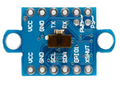
Pin Configuration
The GY-53 VL53L0X module has the following pinout:
| Pin | Name | Description |
|---|---|---|
| 1 | VIN | Power supply input (3.3V to 5V) |
| 2 | GND | Ground connection |
| 3 | SCL | I2C clock line |
| 4 | SDA | I2C data line |
| 5 | XSHUT | Shutdown pin (active low, optional for power control) |
| 6 | GPIO1 | Interrupt output (optional, configurable) |
Usage Instructions
Connecting the GY-53 VL53L0X to an Arduino UNO
To use the GY-53 VL53L0X with an Arduino UNO, follow these steps:
- Connect the VIN pin of the sensor to the 5V pin on the Arduino.
- Connect the GND pin of the sensor to the GND pin on the Arduino.
- Connect the SCL pin of the sensor to the A5 pin on the Arduino (I2C clock line).
- Connect the SDA pin of the sensor to the A4 pin on the Arduino (I2C data line).
- Optionally, connect the XSHUT pin to a digital pin on the Arduino for power control.
Arduino Code Example
Below is an example Arduino sketch to read distance measurements from the GY-53 VL53L0X using the Wire library:
#include <Wire.h>
#include <Adafruit_VL53L0X.h>

// Create an instance of the VL53L0X sensor
Adafruit_VL53L0X lox = Adafruit_VL53L0X();

void setup() {
  Serial.begin(9600); // Initialize serial communication
  while (!Serial) {
    delay(10); // Wait for the serial monitor to open
  }

  Serial.println("Initializing VL53L0X...");

  // Initialize the sensor
  if (!lox.begin()) {
    Serial.println("Failed to find VL53L0X sensor! Check wiring.");
    while (1); // Halt execution if sensor is not found
  }

  Serial.println("VL53L0X ready!");
}

void loop() {
  VL53L0X_RangingMeasurementData_t measure;

  // Perform a distance measurement
  lox.rangingTest(&measure, false);

  // Check if the measurement is valid
  if (measure.RangeStatus != 4) { // 4 indicates an out-of-range error
    Serial.print("Distance: ");
    Serial.print(measure.RangeMilliMeter);
    Serial.println(" mm");
  } else {
    Serial.println("Out of range");
  }

  delay(100); // Wait 100ms before the next measurement
}
Important Considerations
- Ensure the I2C pull-up resistors are present on the SDA and SCL lines. Most Arduino boards have built-in pull-up resistors.
- Avoid exposing the sensor to direct sunlight or reflective surfaces, as this may affect accuracy.
- The XSHUT pin can be used to power down the sensor when not in use, reducing power consumption.
- If multiple VL53L0X sensors are used on the same I2C bus, their addresses must be changed programmatically.
Troubleshooting and FAQs
Common Issues
Sensor not detected by Arduino:
- Verify the wiring connections, especially the SDA and SCL lines.
- Ensure the I2C address (default: 0x29) matches the address in your code.
- Check if the sensor is powered correctly (3.3V to 5V).
Incorrect or fluctuating distance readings:
- Ensure the sensor is not pointed at highly reflective or transparent surfaces.
- Avoid using the sensor in environments with excessive ambient light.
Out-of-range errors:
- Ensure the object is within the sensor's measuring range (30mm to 2 meters).
- Check for obstructions in the sensor's field of view.
FAQs
Q: Can the GY-53 VL53L0X measure distances beyond 2 meters?
A: No, the maximum range of the sensor is 2 meters. Objects beyond this range will result in out-of-range errors.
Q: Can I use the GY-53 VL53L0X with a 3.3V microcontroller?
A: Yes, the sensor is compatible with both 3.3V and 5V logic levels.
Q: How do I change the I2C address of the sensor?
A: The I2C address can be changed programmatically by using the XSHUT pin to reset the sensor and assigning a new address during initialization. Refer to the VL53L0X datasheet for detailed instructions.
Q: Is the laser emitted by the sensor safe?
A: Yes, the VL53L0X uses a Class 1 laser, which is safe under normal operating conditions. Avoid direct eye exposure to the laser.
By following this documentation, you can effectively integrate the GY-53 VL53L0X into your projects for accurate distance measurement.