
How to Use DC-DC Step Up SX1308 Adjustable Power Supply 28V 2A 1.2Mhz Power Booster Module: Examples, Pinouts, and Specs
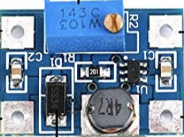
 Design with DC-DC Step Up SX1308 Adjustable Power Supply 28V 2A 1.2Mhz Power Booster Module in Cirkit Designer
Introduction
The DC-DC Step Up SX1308 Adjustable Power Supply Module is a compact and efficient power booster designed to convert a lower DC input voltage to a higher DC output voltage. With an adjustable output range of up to 28V and a maximum current output of 2A, this module is ideal for powering devices that require higher voltages than the input source can provide. Operating at a high switching frequency of 1.2MHz, the SX1308 ensures minimal ripple and high efficiency.
Explore Projects Built with DC-DC Step Up SX1308 Adjustable Power Supply 28V 2A 1.2Mhz Power Booster Module
 Open Project in Cirkit Designer
 Open Project in Cirkit Designer
 Open Project in Cirkit Designer
 Open Project in Cirkit Designer
Explore Projects Built with DC-DC Step Up SX1308 Adjustable Power Supply 28V 2A 1.2Mhz Power Booster Module
Open Project in Cirkit DesignerOpen Project in Cirkit DesignerOpen Project in Cirkit DesignerOpen Project in Cirkit DesignerCommon Applications and Use Cases
- Powering high-voltage devices from low-voltage sources (e.g., batteries, USB power).
- DIY electronics projects requiring adjustable voltage levels.
- LED strips, small motors, and other DC-powered devices.
- Portable power supplies and battery-powered systems.
- Arduino and microcontroller-based projects.
Technical Specifications
Below are the key technical details of the SX1308 module:
| Parameter | Specification |
|---|---|
| Input Voltage Range | 2V to 24V |
| Output Voltage Range | 2V to 28V (adjustable via potentiometer) |
| Maximum Output Current | 2A |
| Switching Frequency | 1.2MHz |
| Efficiency | Up to 93% |
| Dimensions | 22mm x 17mm x 4mm |
Pin Configuration and Descriptions
The SX1308 module has the following pin layout:
| Pin Name | Description |
|---|---|
| VIN | Positive input voltage terminal (connect to the DC power source). |
| GND | Ground terminal (common ground for input and output). |
| VOUT | Positive output voltage terminal (connect to the load). |
| ADJ | Adjustment pin (connected to the onboard potentiometer for voltage adjustment). |
Usage Instructions
How to Use the SX1308 in a Circuit
Connect the Input Voltage:
- Connect the positive terminal of your DC power source to the
VINpin. - Connect the ground terminal of your power source to the
GNDpin.
- Connect the positive terminal of your DC power source to the
Connect the Output Voltage:
- Connect the positive terminal of your load to the
VOUTpin. - Connect the ground terminal of your load to the
GNDpin.
- Connect the positive terminal of your load to the
Adjust the Output Voltage:
- Use a small screwdriver to turn the onboard potentiometer.
- Turning clockwise increases the output voltage, while turning counterclockwise decreases it.
- Use a multimeter to measure the output voltage at
VOUTto ensure it matches your desired value.
Power On:
- Once all connections are secure, power on the input source. The module will boost the input voltage to the desired output level.
Important Considerations and Best Practices
- Input Voltage Range: Ensure the input voltage is within the 2V to 24V range. Exceeding this range may damage the module.
- Output Voltage Limit: Do not exceed the maximum output voltage of 28V or the maximum current of 2A.
- Heat Dissipation: At higher loads, the module may generate heat. Consider adding a heatsink or ensuring proper ventilation.
- Polarity: Double-check the polarity of your connections. Reversing the input or output connections can damage the module.
- Load Testing: Before connecting sensitive devices, test the output voltage and current with a dummy load.
Example: Using the SX1308 with an Arduino UNO
The SX1308 can be used to power an Arduino UNO or other microcontrollers. Below is an example of how to use the module to power an Arduino UNO with a 9V output:
- Set the output voltage of the SX1308 to 9V using the potentiometer.
- Connect the
VOUTpin of the SX1308 to the Arduino's VIN pin. - Connect the
GNDpin of the SX1308 to the Arduino's GND pin.
Here is a simple Arduino code example to blink an LED while powered by the SX1308:
// Simple LED Blink Example
// This code blinks an LED connected to pin 13 of the Arduino UNO.
// Ensure the SX1308 module is providing a stable 9V to the Arduino's VIN pin.

void setup() {
  pinMode(13, OUTPUT); // Set pin 13 as an output pin
}

void loop() {
  digitalWrite(13, HIGH); // Turn the LED on
  delay(1000);            // Wait for 1 second
  digitalWrite(13, LOW);  // Turn the LED off
  delay(1000);            // Wait for 1 second
}
Troubleshooting and FAQs
Common Issues and Solutions
No Output Voltage:
- Cause: Incorrect wiring or insufficient input voltage.
- Solution: Verify all connections and ensure the input voltage is within the specified range.
Output Voltage Not Adjustable:
- Cause: Faulty potentiometer or incorrect adjustment.
- Solution: Check the potentiometer for damage and ensure you are turning it correctly.
Module Overheating:
- Cause: Excessive load or insufficient ventilation.
- Solution: Reduce the load or add a heatsink to the module.
Voltage Drops Under Load:
- Cause: Input power source cannot supply enough current.
- Solution: Use a power source with a higher current rating.
FAQs
Q: Can the SX1308 be used to power a Raspberry Pi?
A: Yes, but ensure the output voltage is set to 5V and the input source can provide sufficient current for both the SX1308 and the Raspberry Pi.
Q: What is the efficiency of the module?
A: The SX1308 has an efficiency of up to 93%, depending on the input voltage, output voltage, and load.
Q: Can I use the SX1308 to charge batteries?
A: While possible, it is not recommended unless you have additional circuitry to regulate the charging process and prevent overcharging.
Q: How do I measure the output voltage?
A: Use a multimeter to measure the voltage across the VOUT and GND pins while the module is powered on.
By following this documentation, you can effectively use the SX1308 module in your projects and troubleshoot common issues.