
How to Use Raspberry Pi Camera Module 3: Examples, Pinouts, and Specs
 Design with Raspberry Pi Camera Module 3 in Cirkit Designer
Introduction
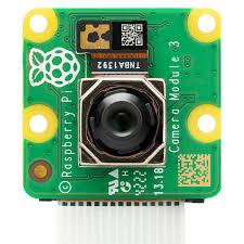
The Raspberry Pi Camera Module 3 is a high-quality camera module designed specifically for Raspberry Pi boards. It features improved image quality, autofocus functionality, and support for 1080p video recording, making it ideal for a wide range of applications. Whether you're building a surveillance system, experimenting with computer vision, or creating a photography project, this camera module offers exceptional performance and versatility.
Explore Projects Built with Raspberry Pi Camera Module 3
 Open Project in Cirkit Designer
 Open Project in Cirkit Designer
 Open Project in Cirkit Designer
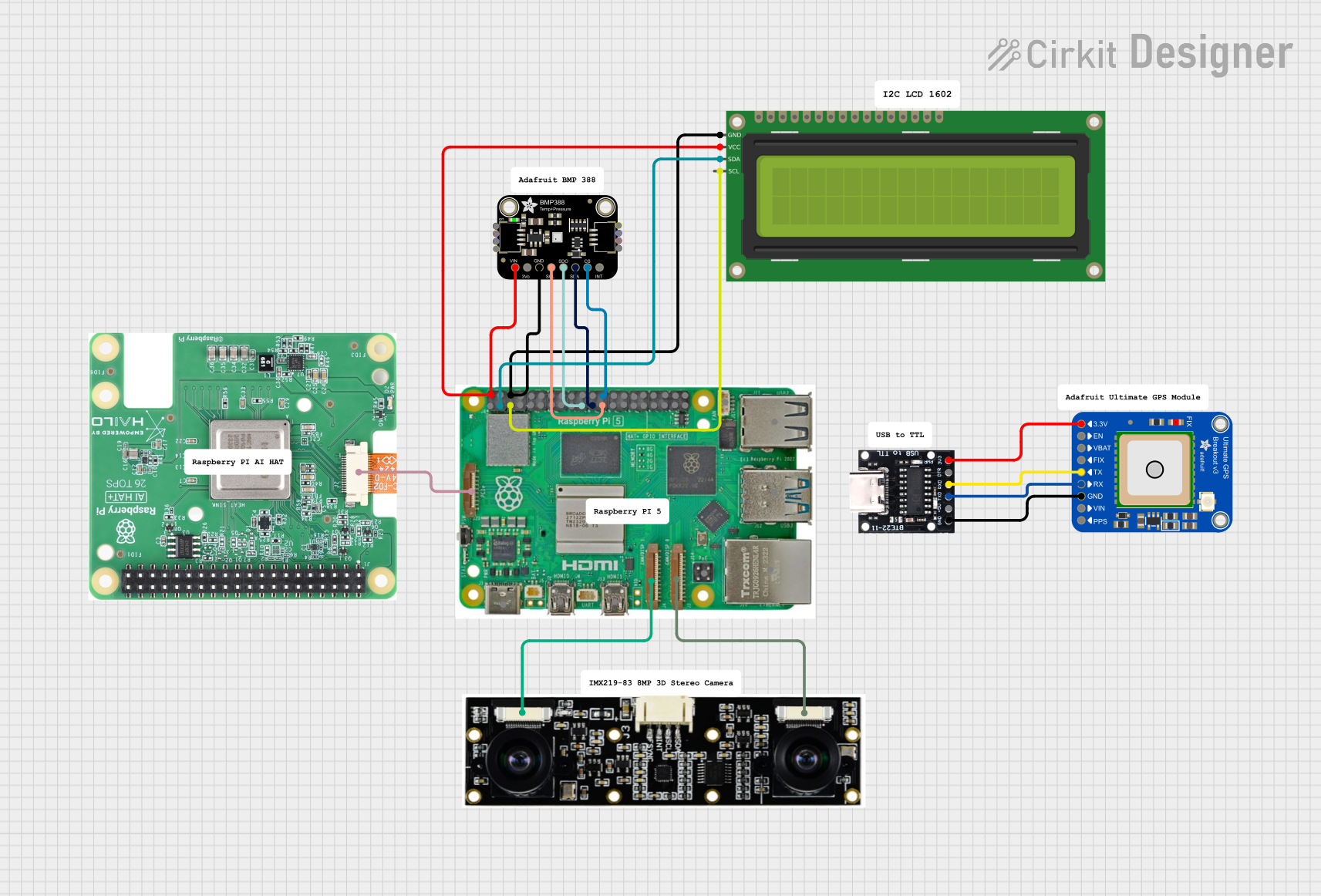 Open Project in Cirkit Designer
Explore Projects Built with Raspberry Pi Camera Module 3
Open Project in Cirkit DesignerOpen Project in Cirkit DesignerOpen Project in Cirkit DesignerOpen Project in Cirkit DesignerCommon Applications and Use Cases
- Surveillance and Security Systems: Capture high-resolution video for monitoring.
- Computer Vision Projects: Use with machine learning models for object detection and recognition.
- Photography and Videography: Take high-quality photos and record 1080p videos.
- Robotics: Enable vision-based navigation and obstacle detection.
- Time-Lapse Photography: Create stunning time-lapse videos with ease.
Technical Specifications
The Raspberry Pi Camera Module 3 is available in multiple variants, including standard and wide-angle lenses, as well as visible light and infrared (NoIR) versions. Below are the key technical details:
Key Specifications
- Sensor: Sony IMX708
- Resolution: 12 megapixels
- Video Recording: Up to 1080p at 50fps
- Autofocus: Yes
- Field of View (FoV):
- Standard: 66° horizontal
- Wide-angle: 102° horizontal
- Connectivity: 22-pin MIPI CSI-2 interface
- Power Supply: 3.3V (via Raspberry Pi)
- Dimensions: 25mm × 24mm × 11.5mm (excluding cable)
Pin Configuration and Descriptions
The Raspberry Pi Camera Module 3 connects to the Raspberry Pi via the Camera Serial Interface (CSI) port using a 22-pin ribbon cable. Below is the pin configuration for the CSI interface:
| Pin Number | Signal Name | Description |
|---|---|---|
| 1 | GND | Ground |
| 2 | CAM_D0_N | Differential data lane 0 (negative) |
| 3 | CAM_D0_P | Differential data lane 0 (positive) |
| 4 | GND | Ground |
| 5 | CAM_D1_N | Differential data lane 1 (negative) |
| 6 | CAM_D1_P | Differential data lane 1 (positive) |
| 7 | GND | Ground |
| 8 | CAM_CLK_N | Differential clock lane (negative) |
| 9 | CAM_CLK_P | Differential clock lane (positive) |
| 10 | GND | Ground |
| 11 | CAM_D2_N | Differential data lane 2 (negative) |
| 12 | CAM_D2_P | Differential data lane 2 (positive) |
| 13 | GND | Ground |
| 14 | CAM_D3_N | Differential data lane 3 (negative) |
| 15 | CAM_D3_P | Differential data lane 3 (positive) |
| 16 | GND | Ground |
| 17 | CAM_IO0 | Camera control signal 0 |
| 18 | CAM_IO1 | Camera control signal 1 |
| 19 | GND | Ground |
| 20 | CAM_IO2 | Camera control signal 2 |
| 21 | CAM_IO3 | Camera control signal 3 |
| 22 | GND | Ground |
Usage Instructions
How to Use the Camera Module in a Circuit
Connect the Camera Module:
- Power off your Raspberry Pi.
- Locate the CSI port on the Raspberry Pi board.
- Insert the ribbon cable from the camera module into the CSI port, ensuring the metal contacts face the correct direction.
- Secure the cable by locking the CSI port's connector.
Enable the Camera Interface:
- Boot up your Raspberry Pi.
- Open a terminal and run the following command to access the Raspberry Pi configuration tool:
sudo raspi-config - Navigate to Interface Options > Camera and enable the camera interface.
- Reboot your Raspberry Pi to apply the changes.
Capture Images and Videos:
- Install the
libcameratools if not already installed:sudo apt update sudo apt install libcamera-apps - Use the following commands to capture images or record videos:
- Capture an image:
libcamera-still -o image.jpg - Record a video:
(Thelibcamera-vid -o video.h264 -t 10000-toption specifies the duration in milliseconds.)
- Capture an image:
- Install the
Important Considerations and Best Practices
- Autofocus Usage: Ensure the subject is within the autofocus range for sharp images.
- Lighting Conditions: Use adequate lighting for better image quality, especially in low-light environments.
- Cable Handling: Avoid bending or damaging the ribbon cable during installation.
- Compatibility: Ensure your Raspberry Pi board supports the Camera Module 3 (e.g., Raspberry Pi 4, 3, or Zero 2 W).
Example Code for Raspberry Pi (Python)
Below is an example Python script to capture an image using the Raspberry Pi Camera Module 3:
from picamera2 import Picamera2
Initialize the camera
picam2 = Picamera2()
Configure the camera for still image capture
picam2.configure(picam2.create_still_configuration())
Start the camera
picam2.start()
Capture an image and save it as 'photo.jpg'
picam2.capture_file("photo.jpg")
Stop the camera
picam2.stop()
print("Image captured and saved as 'photo.jpg'")
Troubleshooting and FAQs
Common Issues and Solutions
Camera Not Detected:
- Ensure the ribbon cable is securely connected to the CSI port.
- Verify that the camera interface is enabled in
raspi-config. - Check for software updates:
sudo apt update && sudo apt upgrade
Poor Image Quality:
- Ensure the lens is clean and free of dust or smudges.
- Use proper lighting to improve image clarity.
- Verify that the autofocus is functioning correctly.
Error: "No data received from sensor":
- Confirm that the camera module is compatible with your Raspberry Pi model.
- Recheck the ribbon cable connection for proper alignment.
Autofocus Not Working:
- Ensure the subject is within the autofocus range (minimum distance: ~10cm).
- Update the camera firmware if autofocus issues persist.
FAQs
Q: Can I use the Camera Module 3 with older Raspberry Pi models?
A: The Camera Module 3 is compatible with Raspberry Pi boards that have a CSI port, but performance may vary on older models.Q: Does the Camera Module 3 support night vision?
A: The NoIR version of the Camera Module 3 is designed for low-light and night vision applications.Q: What is the maximum video resolution and frame rate?
A: The Camera Module 3 supports up to 1080p resolution at 50 frames per second.Q: Can I use multiple camera modules on a single Raspberry Pi?
A: Yes, with the appropriate hardware (e.g., a multi-camera adapter), you can connect multiple camera modules.
This concludes the documentation for the Raspberry Pi Camera Module 3.