
How to Use ESP32-C6-DEV-KIT-NX: Examples, Pinouts, and Specs
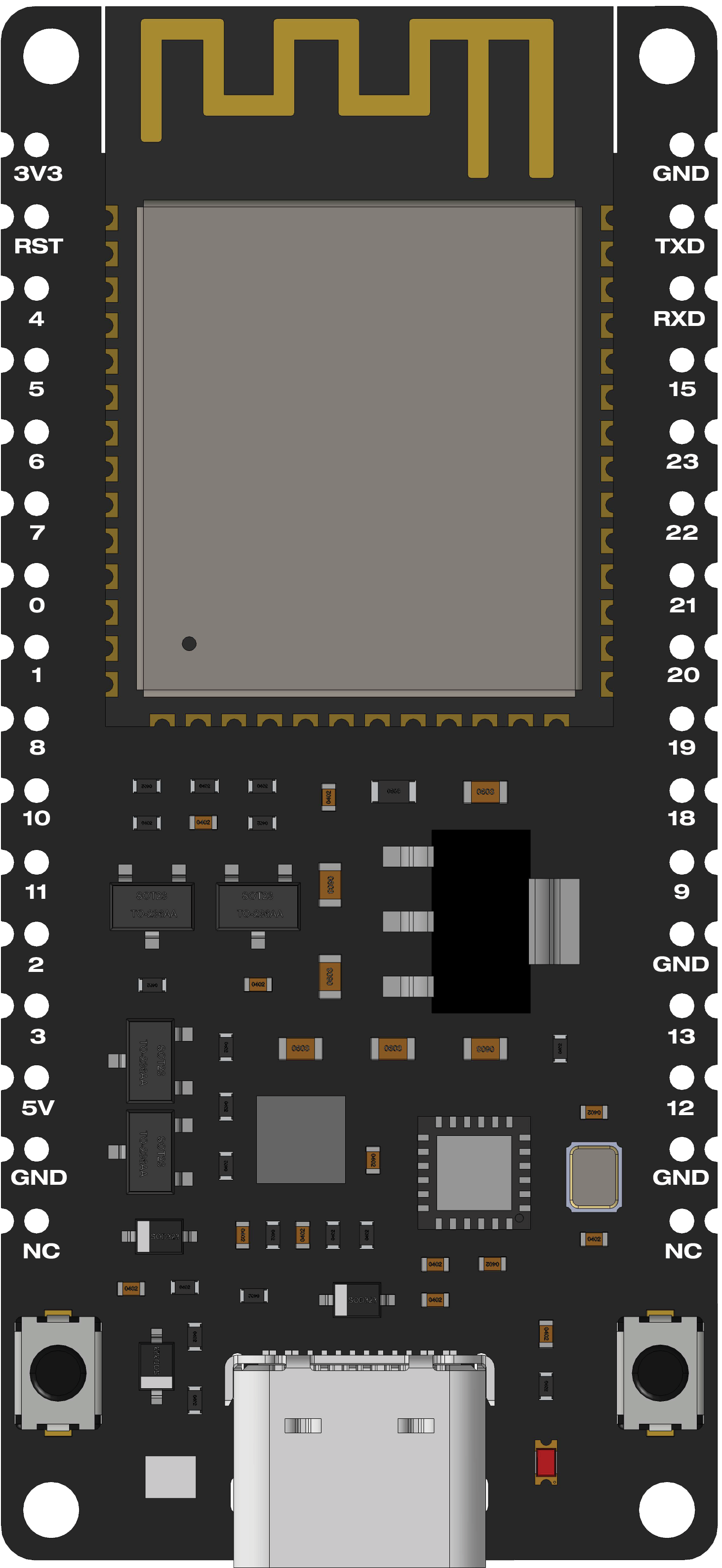
 Design with ESP32-C6-DEV-KIT-NX in Cirkit Designer
Introduction
The ESP32-C6-DEV-KIT-NX is a development board manufactured by Waveshare, featuring the ESP32-C6 chip. This board is designed for IoT applications and prototyping, offering integrated Wi-Fi 6, Bluetooth 5.0, and IEEE 802.15.4 (Thread/Zigbee) capabilities. It is ideal for developers looking to create connected devices with low power consumption and high performance.
Explore Projects Built with ESP32-C6-DEV-KIT-NX
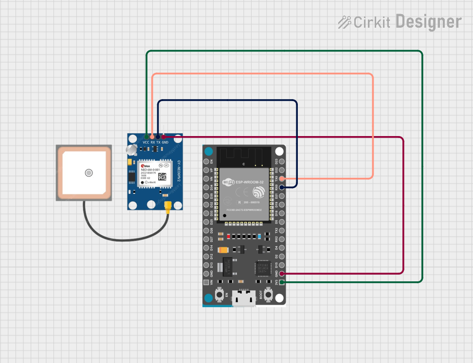 Open Project in Cirkit Designer
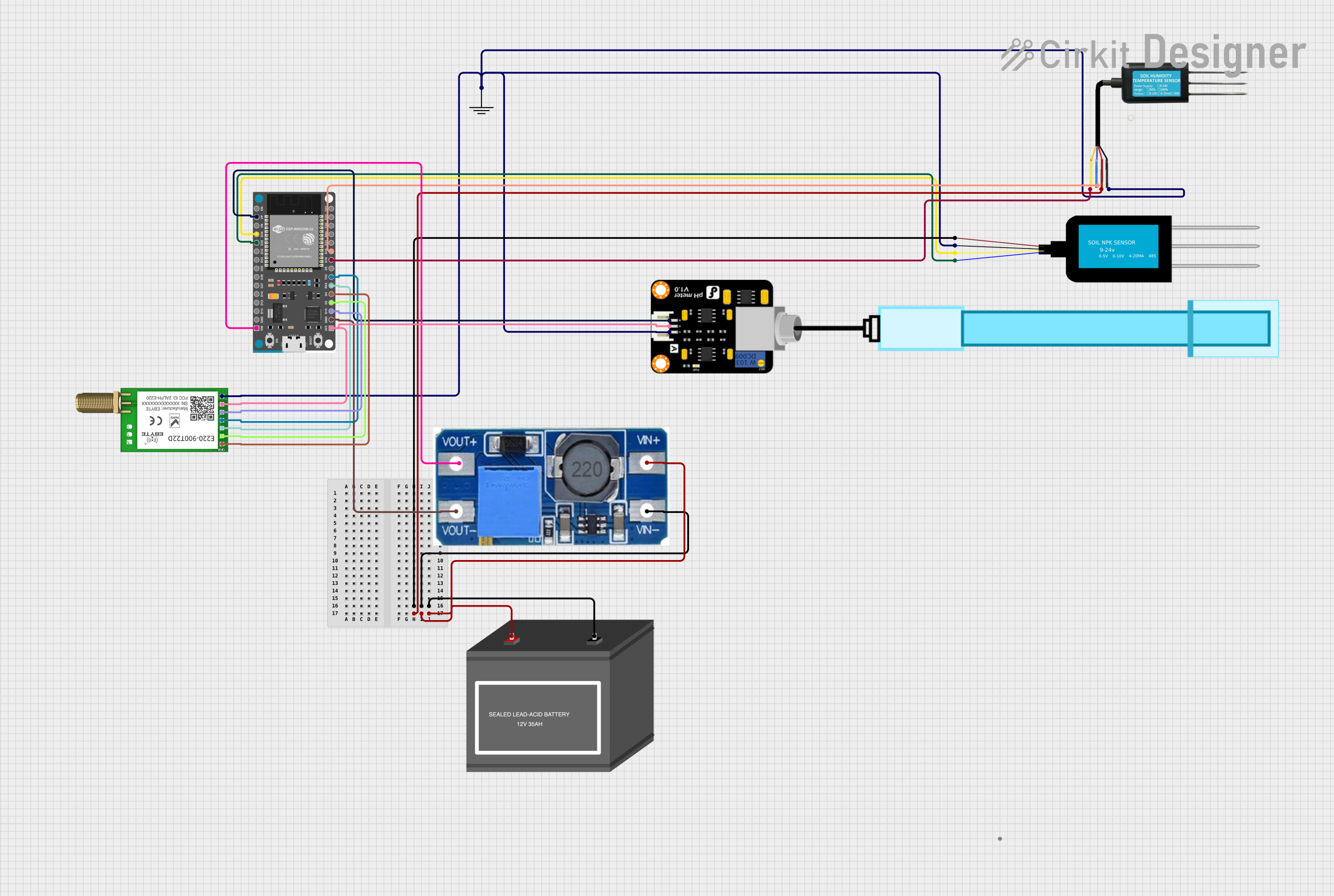 Open Project in Cirkit Designer
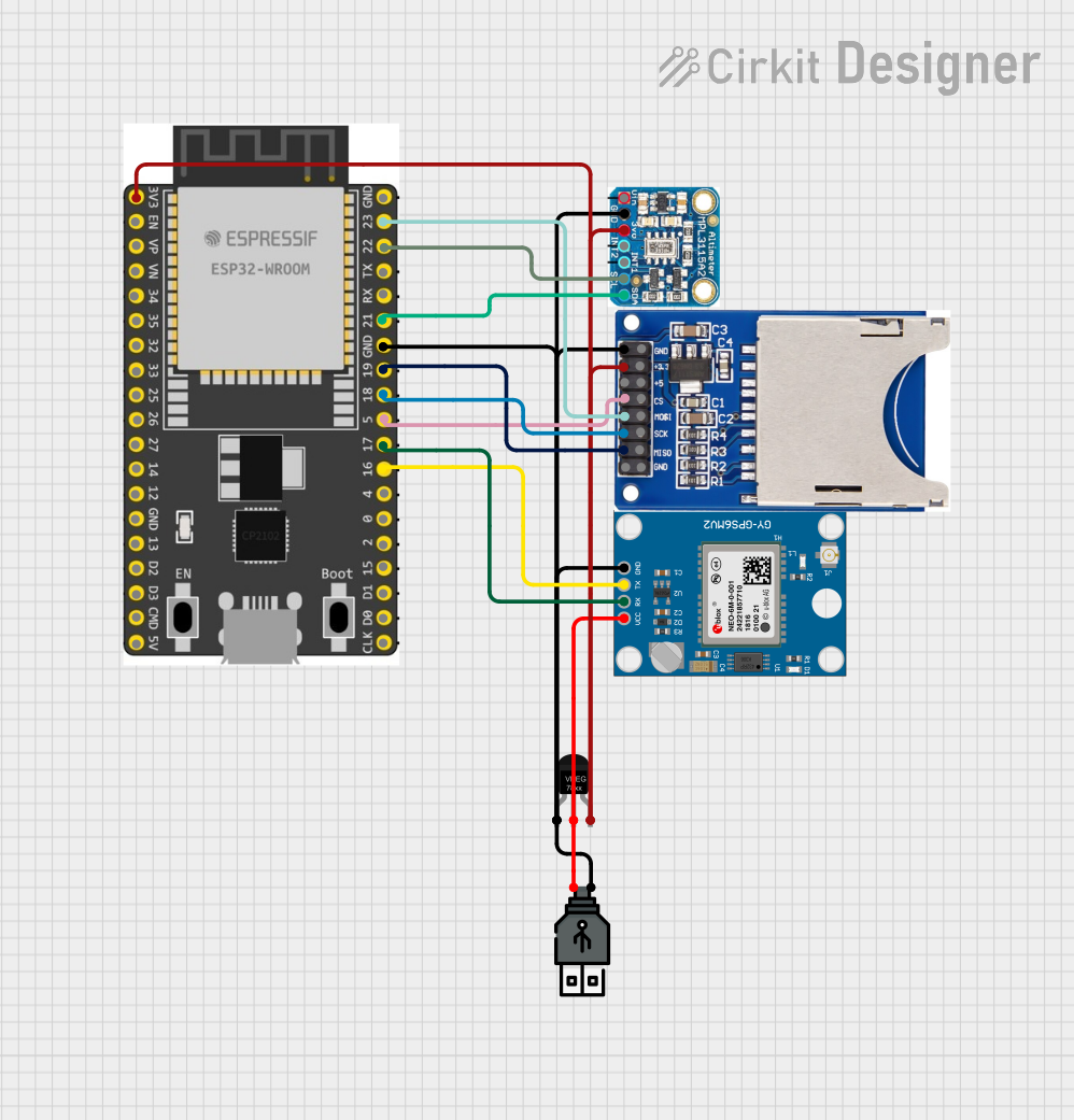 Open Project in Cirkit Designer
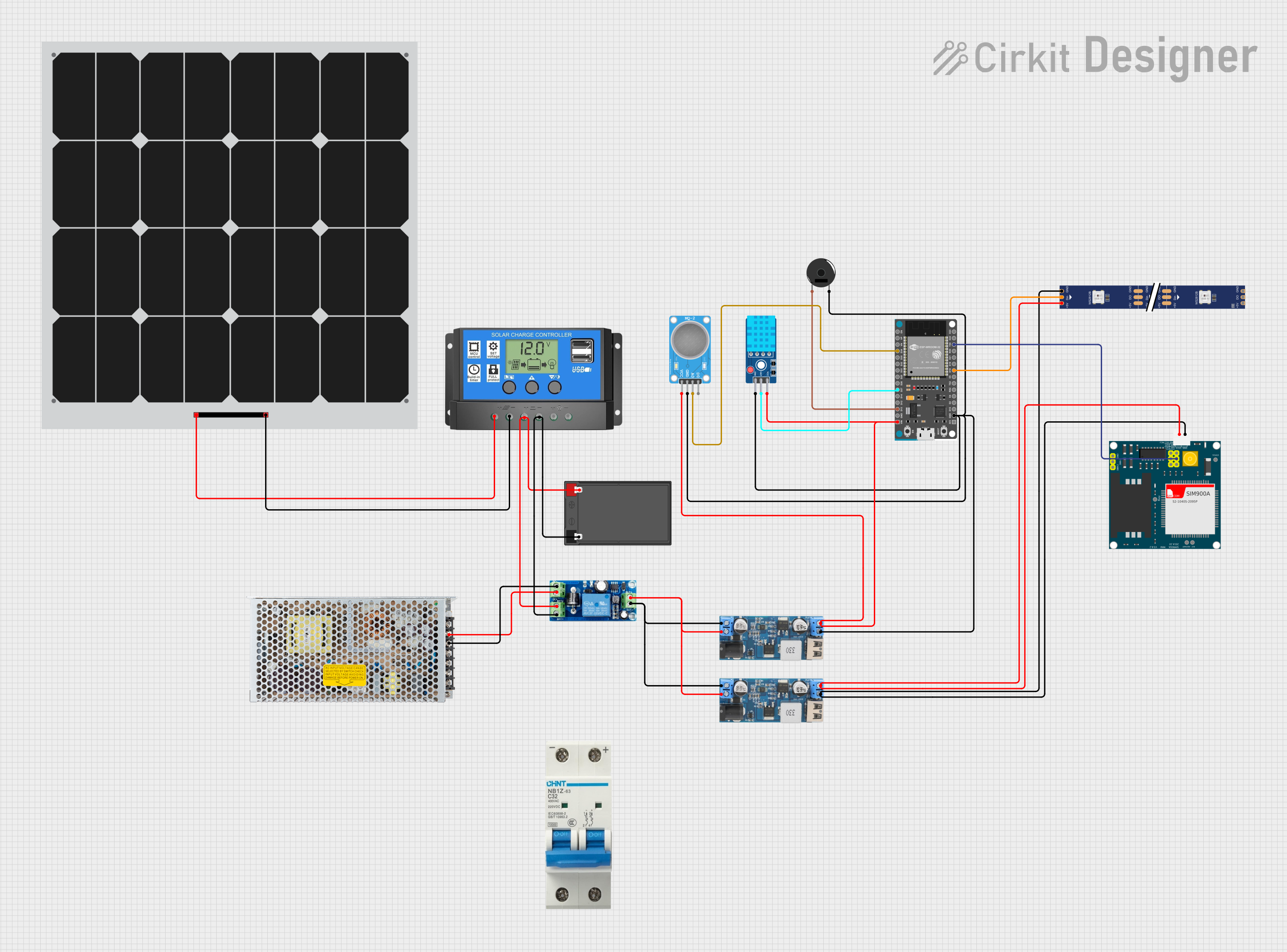 Open Project in Cirkit Designer
Explore Projects Built with ESP32-C6-DEV-KIT-NX
Open Project in Cirkit DesignerOpen Project in Cirkit DesignerOpen Project in Cirkit DesignerOpen Project in Cirkit DesignerCommon Applications and Use Cases
- Smart home devices (e.g., smart lights, thermostats)
- Industrial IoT (IIoT) applications
- Wearable technology
- Wireless sensor networks
- Prototyping for Zigbee or Thread-based systems
- Low-power Bluetooth applications
Technical Specifications
The following table outlines the key technical specifications of the ESP32-C6-DEV-KIT-NX:
| Specification | Details |
|---|---|
| Chipset | ESP32-C6 (RISC-V single-core processor) |
| Wi-Fi | Wi-Fi 6 (802.11ax), 2.4 GHz |
| Bluetooth | Bluetooth 5.0 (LE) |
| IEEE 802.15.4 | Zigbee/Thread support |
| Flash Memory | 4 MB SPI Flash |
| SRAM | 512 KB |
| Operating Voltage | 3.3 V |
| I/O Voltage | 3.3 V (GPIO pins) |
| Power Supply | USB Type-C or external 5 V power supply |
| GPIO Pins | 26 GPIO pins |
| Communication Interfaces | UART, SPI, I2C, I2S, PWM, ADC |
| Operating Temperature | -40°C to +85°C |
| Dimensions | 54 mm x 25 mm |
Pin Configuration and Descriptions
The ESP32-C6-DEV-KIT-NX features a 2-row pin header layout. Below is the pin configuration:
| Pin | Name | Description |
|---|---|---|
| 1 | 3V3 | 3.3 V power output |
| 2 | GND | Ground |
| 3 | GPIO0 | General-purpose I/O, boot mode selection |
| 4 | GPIO1 | General-purpose I/O |
| 5 | GPIO2 | General-purpose I/O |
| 6 | GPIO3 | General-purpose I/O |
| 7 | TXD0 | UART0 transmit |
| 8 | RXD0 | UART0 receive |
| 9 | SDA | I2C data line |
| 10 | SCL | I2C clock line |
| 11 | ADC1_CH0 | Analog-to-digital converter channel 0 |
| 12 | PWM1 | Pulse-width modulation output |
| 13 | EN | Enable pin (active high) |
| 14 | RST | Reset pin |
Note: For a complete pinout diagram, refer to the official Waveshare documentation.
Usage Instructions
How to Use the ESP32-C6-DEV-KIT-NX in a Circuit
Powering the Board:
- Connect the board to your computer or a power source using a USB Type-C cable.
- Alternatively, supply 5 V to the VIN pin and connect GND to the ground.
Programming the Board:
- Install the latest version of the Arduino IDE or ESP-IDF (Espressif IoT Development Framework).
- Add the ESP32-C6 board support package to your development environment.
- Connect the board to your computer and select the appropriate COM port.
Connecting Peripherals:
- Use the GPIO pins to connect sensors, actuators, or other peripherals.
- Ensure that the voltage levels of connected devices are compatible with the 3.3 V logic of the ESP32-C6.
Uploading Code:
- Write your code in the Arduino IDE or ESP-IDF.
- Compile and upload the code to the board via the USB connection.
Important Considerations and Best Practices
- Voltage Levels: Avoid applying voltages higher than 3.3 V to the GPIO pins to prevent damage.
- Boot Mode: To enter bootloader mode, hold the BOOT button while pressing the RESET button.
- Power Supply: Use a stable power source to ensure reliable operation, especially when using Wi-Fi or Bluetooth.
Example Code for Arduino UNO Integration
Below is an example of how to blink an LED connected to GPIO2:
// Define the GPIO pin for the LED
#define LED_PIN 2

void setup() {
  // Set the LED pin as an output
  pinMode(LED_PIN, OUTPUT);
}

void loop() {
  // Turn the LED on
  digitalWrite(LED_PIN, HIGH);
  delay(1000); // Wait for 1 second

  // Turn the LED off
  digitalWrite(LED_PIN, LOW);
  delay(1000); // Wait for 1 second
}
Tip: Ensure that the LED is connected to GPIO2 with a current-limiting resistor (e.g., 220 Ω).
Troubleshooting and FAQs
Common Issues and Solutions
The board is not detected by the computer:
- Ensure the USB cable is functional and supports data transfer.
- Install the necessary USB drivers for the ESP32-C6.
Code upload fails:
- Check that the correct COM port is selected in the development environment.
- Ensure the board is in bootloader mode by holding the BOOT button during upload.
Wi-Fi or Bluetooth is not working:
- Verify that the correct libraries and configurations are included in your code.
- Check for interference or weak signal strength in your environment.
The board overheats:
- Ensure that the power supply voltage does not exceed the recommended range.
- Avoid short circuits on the GPIO pins.
FAQs
Q: Can I use the ESP32-C6-DEV-KIT-NX with Zigbee devices?
A: Yes, the ESP32-C6 supports IEEE 802.15.4, making it compatible with Zigbee and Thread protocols.
Q: What is the maximum Wi-Fi speed supported?
A: The ESP32-C6 supports Wi-Fi 6 (802.11ax) with a maximum theoretical speed of 150 Mbps.
Q: Can I power the board with a battery?
A: Yes, you can use a 3.7 V LiPo battery with a suitable voltage regulator to provide 3.3 V to the board.
Q: Is the ESP32-C6 compatible with Arduino libraries?
A: Yes, many Arduino libraries are compatible with the ESP32-C6, but some may require modifications.
For additional support, refer to the official Waveshare documentation or community forums.