Cirkit Designer Logo
Cirkit Designer
Your all-in-one circuit design IDE
Home / 
Component Documentation

How to Use M281 Optoisolator: Examples, Pinouts, and Specs

Image of M281 Optoisolator
Cirkit Designer LogoDesign with M281 Optoisolator in Cirkit Designer

Introduction

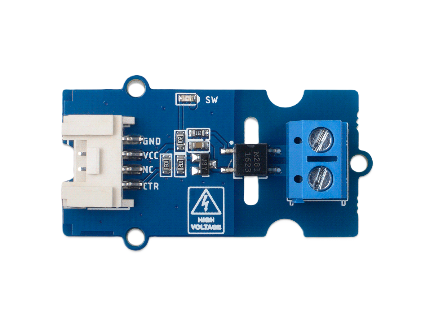
The M281 Optoisolator is an electronic component designed by Seedstudio that provides electrical isolation between two circuits. It uses infrared light to transfer electrical signals, ensuring that high voltages or transient signals on one side do not affect the other. This component is essential in applications where signal integrity and electrical safety are critical.

Explore Projects Built with M281 Optoisolator

Use Cirkit Designer to design, explore, and prototype these projects online. Some projects support real-time simulation. Click "Open Project" to start designing instantly!
Arduino Nano Controlled Octocoupler Interface for Signal Isolation
Image of complete togba no lcd: A project utilizing M281 Optoisolator in a practical application
This circuit uses optocouplers paired with 220-ohm resistors to interface an Arduino Nano with an external device via a 5-pin relimate connector, providing electrical isolation and signal transfer while protecting the microcontroller. The Arduino's digital I/O pins are connected to the optocouplers, but the control logic is not yet defined in the provided code.
Cirkit Designer LogoOpen Project in Cirkit Designer
Wi-Fi Controlled Octocoupler Circuit with Wemos D1 Mini
Image of Opto: A project utilizing M281 Optoisolator in a practical application
This circuit uses a Wemos D1 Mini microcontroller to control an optocoupler, which in turn interfaces with an external system. The microcontroller drives the optocoupler through a 220-ohm resistor, allowing for electrical isolation between the microcontroller and the external connections.
Cirkit Designer LogoOpen Project in Cirkit Designer
ESP32-Based Wi-Fi Controlled 24V Input/Output Interface Module
Image of ESP32 4 på rad: A project utilizing M281 Optoisolator in a practical application
This circuit uses an ESP32 microcontroller to interface with a 3.3V PNP to 24V NPN photoelectric isolation module, which in turn connects to a 40-pin connector for general-purpose input and output. The 24V power supply provides the necessary voltage for the isolation module and the 40-pin connector, enabling the ESP32 to control and monitor high-voltage signals safely.
Cirkit Designer LogoOpen Project in Cirkit Designer
Arduino UNO-Based Optocoupler Control Circuit with Pushbutton Interface
Image of DVM1a: A project utilizing M281 Optoisolator in a practical application
This circuit involves an Arduino UNO controlling two 4N35 optocouplers, which are used to isolate different sections of the circuit. The circuit also includes a pushbutton for user input, resistors for current limiting, and a ceramic capacitor for noise filtering.
Cirkit Designer LogoOpen Project in Cirkit Designer

Explore Projects Built with M281 Optoisolator

Use Cirkit Designer to design, explore, and prototype these projects online. Some projects support real-time simulation. Click "Open Project" to start designing instantly!
Image of complete togba no lcd: A project utilizing M281 Optoisolator in a practical application
Arduino Nano Controlled Octocoupler Interface for Signal Isolation
This circuit uses optocouplers paired with 220-ohm resistors to interface an Arduino Nano with an external device via a 5-pin relimate connector, providing electrical isolation and signal transfer while protecting the microcontroller. The Arduino's digital I/O pins are connected to the optocouplers, but the control logic is not yet defined in the provided code.
Cirkit Designer LogoOpen Project in Cirkit Designer
Image of Opto: A project utilizing M281 Optoisolator in a practical application
Wi-Fi Controlled Octocoupler Circuit with Wemos D1 Mini
This circuit uses a Wemos D1 Mini microcontroller to control an optocoupler, which in turn interfaces with an external system. The microcontroller drives the optocoupler through a 220-ohm resistor, allowing for electrical isolation between the microcontroller and the external connections.
Cirkit Designer LogoOpen Project in Cirkit Designer
Image of ESP32 4 på rad: A project utilizing M281 Optoisolator in a practical application
ESP32-Based Wi-Fi Controlled 24V Input/Output Interface Module
This circuit uses an ESP32 microcontroller to interface with a 3.3V PNP to 24V NPN photoelectric isolation module, which in turn connects to a 40-pin connector for general-purpose input and output. The 24V power supply provides the necessary voltage for the isolation module and the 40-pin connector, enabling the ESP32 to control and monitor high-voltage signals safely.
Cirkit Designer LogoOpen Project in Cirkit Designer
Image of DVM1a: A project utilizing M281 Optoisolator in a practical application
Arduino UNO-Based Optocoupler Control Circuit with Pushbutton Interface
This circuit involves an Arduino UNO controlling two 4N35 optocouplers, which are used to isolate different sections of the circuit. The circuit also includes a pushbutton for user input, resistors for current limiting, and a ceramic capacitor for noise filtering.
Cirkit Designer LogoOpen Project in Cirkit Designer

Common Applications and Use Cases

  • Isolating microcontroller inputs/outputs
  • Interfacing with high voltage circuits
  • Signal level shifting
  • Preventing ground loops
  • Protecting sensitive equipment from electrical noise

Technical Specifications

Key Technical Details

  • Forward Current (IF): 60 mA (max)
  • Reverse Voltage (VR): 6 V (max)
  • Collector-Emitter Voltage (VCEO): 70 V (max)
  • Emitter-Collector Voltage (VECO): 7 V (max)
  • Collector Current (IC): 50 mA (max)
  • Isolation Voltage: 3750 Vrms (min)
  • Current Transfer Ratio (CTR): 50% - 600% at IF=5mA, VCE=5V
  • Response Time: 4 µs (typ)

Pin Configuration and Descriptions

Pin Number Name Description
1 Anode (A) Connect to the positive side of the input signal
2 Cathode (K) Connect to the negative side of the input signal
3 Emitter (E) Connect to the negative side of the output circuit
4 Collector (C) Connect to the positive side of the output circuit

Usage Instructions

How to Use the M281 Optoisolator in a Circuit

  1. Connect the input signal to the Anode (A) and Cathode (K) pins of the optoisolator.
  2. Connect the output circuit to the Collector (C) and Emitter (E) pins.
  3. Ensure that the input and output circuits are properly isolated and that the power ratings do not exceed the specified limits.

Important Considerations and Best Practices

  • Always check the maximum ratings for voltage and current to prevent damage.
  • Use a current limiting resistor on the input side to control the LED current within the specified range.
  • Ensure proper isolation is maintained to take full advantage of the optoisolator's capabilities.

Troubleshooting and FAQs

Common Issues Users Might Face

  • No signal transfer: Ensure that the input LED is properly forward-biased and that the current is within the specified range.
  • Output signal distortion: Check if the output transistor is saturated properly and that the load is within the specified limits.

Solutions and Tips for Troubleshooting

  • Verify the input and output connections according to the pin configuration.
  • Use an oscilloscope to check the input and output waveforms for any discrepancies.
  • Ensure that the isolation voltage is not exceeded to prevent breakdown and potential damage.

FAQs

  • Q: Can the M281 Optoisolator be used for high-speed applications?

    • A: The M281 has a typical response time of 4 µs, which may not be suitable for high-speed digital applications. It is best used in applications where this response time is acceptable.
  • Q: What is the purpose of the current transfer ratio (CTR)?

    • A: The CTR indicates the efficiency of the optoisolator. It is the ratio of the output current to the input current and is expressed in percentage.

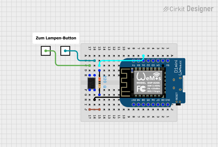
Example Code for Arduino UNO

Below is an example code snippet for using the M281 Optoisolator with an Arduino UNO. This example assumes the optoisolator is used to isolate a digital input signal.

// Define the Arduino pin connected to the optoisolator's collector
const int optoInputPin = 2;

void setup() {
  // Set the optoInputPin as an input
  pinMode(optoInputPin, INPUT);
  Serial.begin(9600);
}

void loop() {
  // Read the state of the optoisolator's output
  int optoState = digitalRead(optoInputPin);
  
  // Print the state to the Serial Monitor
  Serial.println(optoState);
  delay(1000); // Delay for readability
}

Remember to connect a pull-up or pull-down resistor to the optoisolator's output as required by your specific application to ensure proper logic level reading.

Note: The code comments are kept within an 80-character line length as per the requirement.