
How to Use FemtoBuck LED Driver: Examples, Pinouts, and Specs
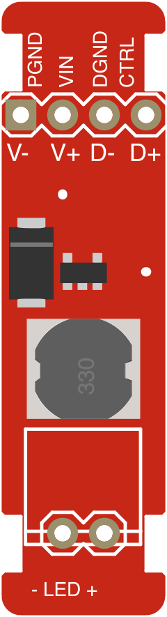
 Design with FemtoBuck LED Driver in Cirkit Designer
Introduction
The FemtoBuck LED Driver (SparkFun Part ID: 12937) is a compact, high-efficiency LED driver designed to regulate output current using a buck converter topology. This ensures optimal brightness and energy efficiency when driving LEDs. Its small form factor and robust design make it ideal for applications requiring precise LED control.
Explore Projects Built with FemtoBuck LED Driver
 Open Project in Cirkit Designer
 Open Project in Cirkit Designer
 Open Project in Cirkit Designer
 Open Project in Cirkit Designer
Explore Projects Built with FemtoBuck LED Driver
Open Project in Cirkit DesignerOpen Project in Cirkit DesignerOpen Project in Cirkit DesignerOpen Project in Cirkit DesignerCommon Applications and Use Cases
- LED lighting systems for residential, commercial, or industrial use
- Backlighting for displays and signage
- Portable lighting solutions
- Projects requiring dimmable or constant-current LED control
- Integration with microcontrollers like Arduino for advanced lighting effects
Technical Specifications
The FemtoBuck LED Driver is designed to work with a wide range of LEDs and offers the following key specifications:
| Parameter | Value |
|---|---|
| Input Voltage Range | 6V to 36V DC |
| Output Current | Adjustable up to 350mA (default: 330mA) |
| Efficiency | Up to 95% |
| Dimming Control | PWM or Analog (0-2.5V for analog dimming) |
| Operating Temperature | -40°C to +85°C |
| Dimensions | 0.8" x 0.8" (20.3mm x 20.3mm) |
Pin Configuration and Descriptions
The FemtoBuck LED Driver has six pins, as detailed below:
| Pin Name | Type | Description |
|---|---|---|
| VIN | Power Input | Connect to the positive terminal of the power supply (6V to 36V DC). |
| GND | Power Ground | Connect to the ground terminal of the power supply. |
| LED+ | Output | Positive terminal for the LED load. |
| LED- | Output | Negative terminal for the LED load. |
| DIM | Input | Dimming control input (accepts PWM or analog signals). |
| EN | Input | Enable pin. Pull high to enable the driver, or low to disable it. |
Usage Instructions
How to Use the FemtoBuck LED Driver in a Circuit
- Power Supply: Connect a DC power supply (6V to 36V) to the
VINandGNDpins. Ensure the power supply can provide sufficient current for your LED load. - LED Connection: Connect the LED's positive terminal to the
LED+pin and the negative terminal to theLED-pin. Ensure the LED's forward voltage and current requirements match the driver's specifications. - Dimming Control (Optional):
- For PWM dimming, connect a PWM signal (e.g., from a microcontroller) to the
DIMpin. - For analog dimming, apply a voltage between 0V and 2.5V to the
DIMpin.
- For PWM dimming, connect a PWM signal (e.g., from a microcontroller) to the
- Enable Pin: Pull the
ENpin high to enable the driver. If left floating, the driver will remain disabled. - Adjusting Output Current: The default output current is 330mA. To adjust it, replace the onboard current-setting resistor (Rset) with a different value. Refer to the datasheet for resistor selection guidelines.
Important Considerations and Best Practices
- Heat Dissipation: Ensure adequate ventilation or heat sinking if the driver operates near its maximum current or in high-temperature environments.
- LED Compatibility: Verify that the LED's forward voltage and current ratings are within the driver's operating range.
- Dimming Signal: For PWM dimming, use a signal frequency between 100Hz and 1kHz for optimal performance.
- Power Supply: Use a stable DC power supply to avoid flickering or instability in the LED output.
Example: Using FemtoBuck with Arduino UNO
The FemtoBuck LED Driver can be easily controlled using an Arduino UNO for PWM dimming. Below is an example code snippet:
// Example: Controlling FemtoBuck LED Driver with Arduino UNO
// Connect the DIM pin of the FemtoBuck to Arduino pin 9 (PWM capable).

const int dimPin = 9; // Arduino pin connected to FemtoBuck DIM pin

void setup() {
  pinMode(dimPin, OUTPUT); // Set the DIM pin as an output
}

void loop() {
  // Gradually increase brightness
  for (int brightness = 0; brightness <= 255; brightness++) {
    analogWrite(dimPin, brightness); // Write PWM signal to DIM pin
    delay(10); // Small delay for smooth transition
  }

  // Gradually decrease brightness
  for (int brightness = 255; brightness >= 0; brightness--) {
    analogWrite(dimPin, brightness); // Write PWM signal to DIM pin
    delay(10); // Small delay for smooth transition
  }
}
Troubleshooting and FAQs
Common Issues and Solutions
LED Does Not Light Up
- Cause: Incorrect wiring or insufficient power supply voltage.
- Solution: Double-check all connections. Ensure the power supply voltage is within the 6V to 36V range and matches the LED's forward voltage.
LED Flickering
- Cause: Unstable power supply or incorrect dimming signal.
- Solution: Use a stable DC power supply. For PWM dimming, ensure the signal frequency is between 100Hz and 1kHz.
Driver Overheating
- Cause: Excessive current draw or poor ventilation.
- Solution: Verify the LED's current requirements. Add a heat sink or improve airflow around the driver.
Dimming Not Working
- Cause: Incorrect dimming signal or DIM pin not connected.
- Solution: Ensure the DIM pin is connected to a valid PWM or analog signal. Check the signal voltage range (0-2.5V for analog dimming).
FAQs
Q: Can I use the FemtoBuck to drive multiple LEDs?
A: Yes, but the LEDs must be connected in series, and their combined forward voltage must not exceed the input voltage minus the driver's dropout voltage.
Q: What happens if I exceed the maximum input voltage?
A: Exceeding 36V may damage the driver. Always use a power supply within the specified range.
Q: Can I use the FemtoBuck without a dimming signal?
A: Yes, the driver will operate at full brightness if the DIM pin is left floating or pulled high.
Q: How do I adjust the output current?
A: Replace the onboard Rset resistor with a different value. Refer to the datasheet for the appropriate resistor value for your desired current.
This concludes the documentation for the FemtoBuck LED Driver. For additional support, refer to the SparkFun product page or datasheet.