How to Use ESP32 Terminal adapter 38 pin: Examples, Pinouts, and Specs
Introduction
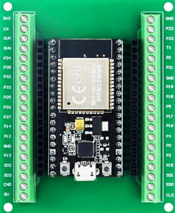
The ESP32 Terminal Adapter 38 Pin is a versatile breakout board designed to simplify the use of the ESP32 microcontroller. Manufactured by ESP, this adapter provides a convenient way to access all 38 pins of the ESP32, making it ideal for prototyping and development. It features labeled pin headers for easy identification and connection to peripherals, sensors, and other components.
Explore Projects Built with ESP32 Terminal adapter 38 pin
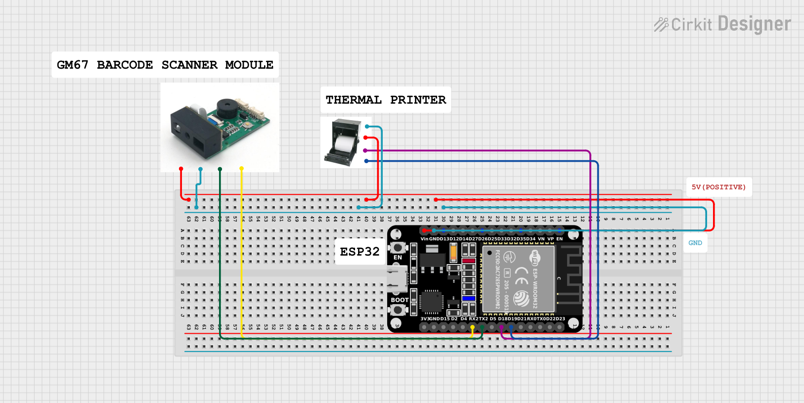

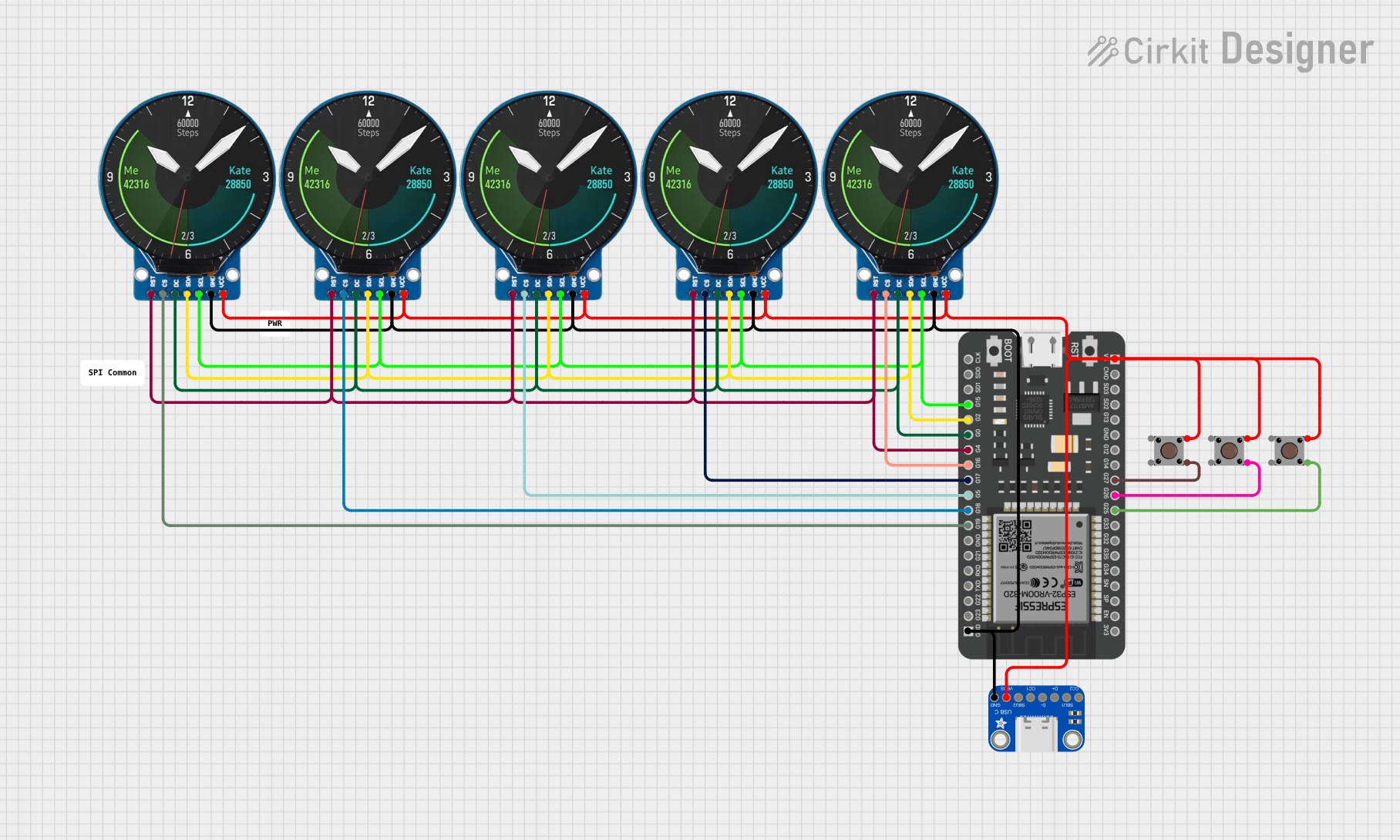

Explore Projects Built with ESP32 Terminal adapter 38 pin
Common Applications and Use Cases
- Rapid prototyping of IoT (Internet of Things) devices
- Development of smart home automation systems
- Integration with sensors, actuators, and displays
- Educational projects and learning platforms
- Wireless communication projects using Wi-Fi and Bluetooth
Technical Specifications
The following table outlines the key technical details of the ESP32 Terminal Adapter 38 Pin:
| Parameter | Specification |
|---|---|
| Manufacturer | ESP |
| Part ID | 32 |
| Number of Pins | 38 |
| Supported Microcontroller | ESP32 |
| Voltage Input Range | 3.3V to 5V |
| Dimensions | 57mm x 25mm x 12mm |
| Pin Type | Male headers |
| Compatibility | Breadboards, jumper wires, and other prototyping tools |
Pin Configuration and Descriptions
The ESP32 Terminal Adapter provides access to all 38 pins of the ESP32 microcontroller. Below is a table describing the pin configuration:
| Pin Name | Description | Functionality |
|---|---|---|
| VIN | Voltage input (3.3V to 5V) | Power supply for the ESP32 |
| GND | Ground | Common ground for the circuit |
| 3V3 | 3.3V output | Power output for peripherals |
| EN | Enable pin | Enables or disables the ESP32 |
| IO0 - IO39 | General-purpose I/O pins | Digital/analog input/output |
| TXD0, RXD0 | UART0 transmit/receive | Serial communication |
| SCL, SDA | I2C clock and data lines | I2C communication |
| MOSI, MISO, SCK, CS | SPI interface pins | SPI communication |
| ADC1, ADC2 | Analog-to-digital converter channels | Analog input |
| DAC1, DAC2 | Digital-to-analog converter channels | Analog output |
| RST | Reset pin | Resets the ESP32 |
Usage Instructions
How to Use the ESP32 Terminal Adapter in a Circuit
- Powering the Adapter: Connect the VIN pin to a 5V power source or use the 3.3V pin for a regulated 3.3V supply. Ensure the GND pin is connected to the common ground of your circuit.
- Connecting Peripherals: Use jumper wires to connect sensors, actuators, or other components to the labeled pins on the adapter.
- Programming the ESP32: Use a USB-to-serial adapter or a development board with built-in USB support to upload code to the ESP32 microcontroller.
- Breadboard Compatibility: The adapter is designed to fit standard breadboards, allowing for easy prototyping.
Important Considerations and Best Practices
- Voltage Levels: Ensure that all connected peripherals operate within the 3.3V logic level of the ESP32. Use level shifters if interfacing with 5V devices.
- Pin Usage: Avoid using reserved pins (e.g., IO0, IO2) for general I/O unless necessary, as they may interfere with boot modes.
- Power Supply: Use a stable power source to prevent unexpected resets or malfunctions.
- Heat Management: The ESP32 may generate heat during operation. Ensure proper ventilation or use a heatsink if required.
Example Code for Arduino UNO Integration
Below is an example of how to use the ESP32 Terminal Adapter with an Arduino IDE to blink an LED connected to GPIO2:
// Example: Blink an LED connected to GPIO2 on the ESP32 Terminal Adapter

// Define the GPIO pin for the LED
#define LED_PIN 2

void setup() {
  // Initialize the LED pin as an output
  pinMode(LED_PIN, OUTPUT);
}

void loop() {
  // Turn the LED on
  digitalWrite(LED_PIN, HIGH);
  delay(1000); // Wait for 1 second

  // Turn the LED off
  digitalWrite(LED_PIN, LOW);
  delay(1000); // Wait for 1 second
}
Troubleshooting and FAQs
Common Issues and Solutions
ESP32 Not Powering On
- Cause: Insufficient or incorrect power supply.
- Solution: Ensure the VIN pin is connected to a 5V source or use a regulated 3.3V supply.
Unable to Upload Code
- Cause: Incorrect boot mode or serial connection.
- Solution: Check that the EN and IO0 pins are correctly configured for programming mode. Ensure the USB-to-serial adapter is properly connected.
Peripheral Not Responding
- Cause: Incorrect wiring or voltage mismatch.
- Solution: Verify connections and ensure peripherals are compatible with the ESP32's 3.3V logic level.
ESP32 Overheating
- Cause: High current draw or poor ventilation.
- Solution: Reduce the load on the ESP32 or improve airflow around the adapter.
FAQs
Q: Can I use the ESP32 Terminal Adapter with a 5V logic device?
- A: No, the ESP32 operates at 3.3V logic. Use a level shifter for compatibility with 5V devices.
Q: Is the adapter compatible with all ESP32 modules?
- A: The adapter is designed for ESP32 modules with a 38-pin configuration. Ensure your module matches this layout.
Q: How do I reset the ESP32?
- A: Use the RST pin or press the reset button (if available) on the ESP32 module.
This documentation provides a comprehensive guide to using the ESP32 Terminal Adapter 38 Pin for your projects. Happy prototyping!